Optical lens, camera module and assembling method thereof

An optical lens and assembly method technology, applied in the field of optical imaging, can solve problems such as poor product and image quality deterioration, and achieve the effects of reducing deformation, reducing lens position shift, and increasing strength

Active Publication Date: 2019-12-10
NINGBO SUNNY OPOTECH CO LTD
View PDF8 Cites 4 Cited by
  • Summary
  • Abstract
  • Description
  • Claims
  • Application Information

AI Technical Summary

Problems solved by technology

However, the actual trial production found that the imaging quality of the optical lens and camera module often deteriorates compared with the imaging quality obtained in the active calibration stage. This degradation sometimes exceeds the tolerance range, resulting in defective products
The applicant's research found that after the active calibration process was introduced into the assembly of the optical lens or camera module, the variation of the glue material, lens barrel or lens, and other unknown factors may be the cause of the above problems

Method used


Image

  • Optical lens, camera module and assembling method thereof
  • Optical lens, camera module and assembling method thereof
  • Optical lens, camera module and assembling method thereof

Examples


Embodiment Construction

[0089] For a better understanding of the application, various aspects of the application will be described in more detail with reference to the accompanying drawings. It should be understood that these detailed descriptions are descriptions of exemplary embodiments of the application only, and are not intended to limit the scope of the application in any way. Throughout the specification, the same reference numerals refer to the same elements. The expression "and / or" includes any and all combinations of one or more of the associated listed items.

[0090] It should be noted that in this specification, expressions of first, second, etc. are only used to distinguish one feature from another, and do not represent any limitation on the features. Accordingly, a first body discussed hereinafter may also be referred to as a second body without departing from the teachings of the present application.

[0091] In the drawings, the thickness, size and shape of objects have been slight...


PUM


Abstract

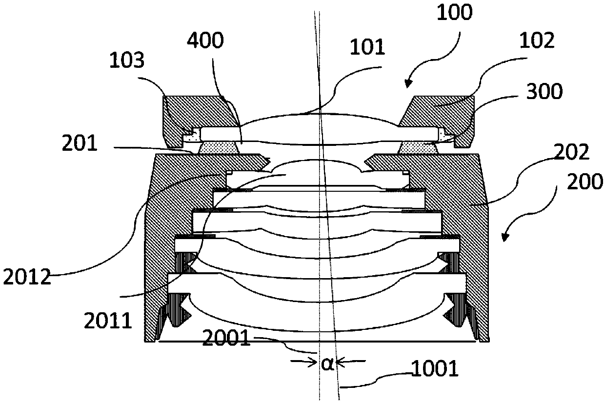
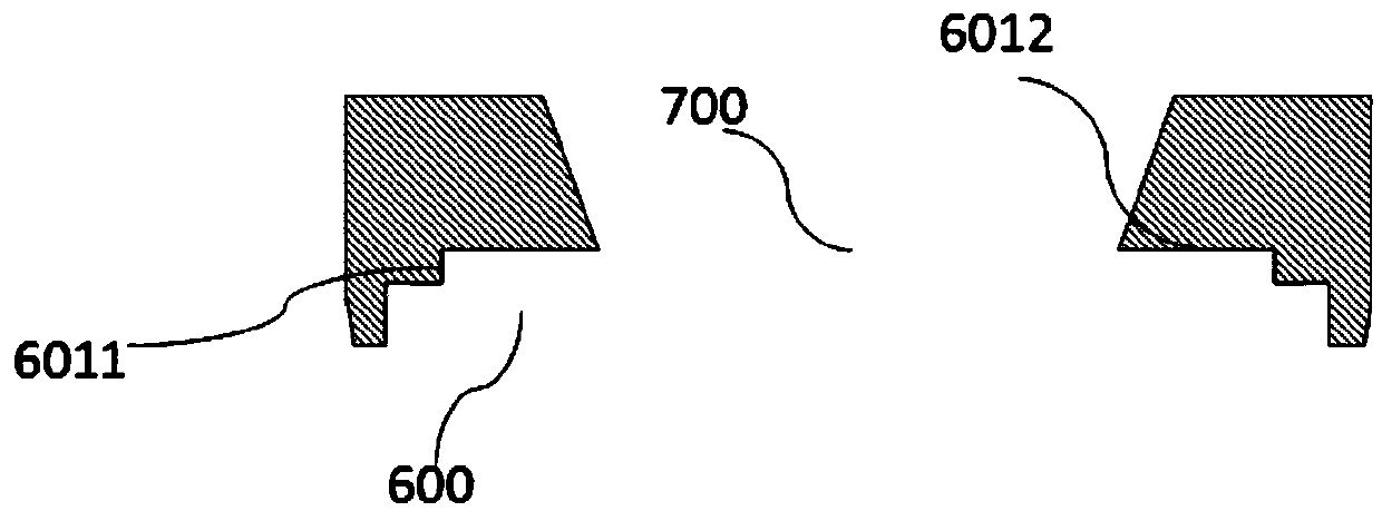
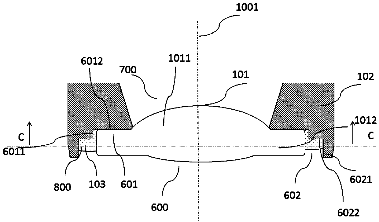
The invention provides an optical lens. The optical lens comprises a first lens part, a second lens part and a first adhesive material, wherein the first lens component comprises a first lens barrel and at least one first lens, and the second lens component comprises a second lens barrel and at least one second lens. All the second lenses and all the first lenses form an imageable optical system,the inner side of the first lens barrel is provided with a first accommodating hole, at least one of the first lenses is embedded into the first accommodating hole; the embedded first lens is providedwith a first outer side surface, and the first outer side surface comprises a contact part which is in direct contact with the side surface of the first accommodating hole and forms close fit with the side surface of the first accommodating hole; and a non-contact part which is not in direct contact with the side surface of the first accommodating hole, and is bonded with the first lens cone through the bonding glue. The invention further provides a corresponding assembling method of the optical lens and the camera module. According to the invention, the lens position offset caused by lens cone deformation can be reduced, the imaging quality of the optical lens or the camera module can be improved.

Description

technical field [0001] The invention relates to the technical field of optical imaging, in particular, the invention relates to an optical lens, a camera module and an assembly method thereof. Background technique [0002] With the popularization of mobile electronic devices, related technologies of camera modules used in mobile electronic devices to help users acquire images (such as video or images) have developed rapidly and improved rapidly, and in recent years, camera modules Groups have been widely used in many fields such as medical treatment, security, industrial production and so on. [0003] In order to meet more and more extensive market demands, high pixel, small size, and large aperture are irreversible development trends of existing camera modules. However, it is very difficult to achieve the three requirements of high pixel, small size and large aperture in the same camera mold. For example, the compact development of mobile phones and the increase in screen...

Claims


Application Information

Patent Timeline
Patent Type & Authority Applications(China)
IPC IPC(8): G02B7/02
CPCG02B7/021G02B7/025
Inventor 田中武彦梅其敏蒋恒
Owner NINGBO SUNNY OPOTECH CO LTD
Why Eureka
Try Eureka