Supercharge Your Innovation With Domain-Expert AI Agents!

Pole piece processing equipment

A processing equipment and pole piece technology, applied in the field of pole piece processing equipment, can solve the problems of reducing the quality of pole piece cutting, the quality of tab forming, reducing the cutting stability of the cutting mechanism, and the waste cost of pole pieces, etc. The effect of cutting stability, improving cutting quality and reducing processing cost

Pending Publication Date: 2019-12-10
CONTEMPORARY AMPEREX TECH CO
View PDF0 Cites 4 Cited by
  • Summary
  • Abstract
  • Description
  • Claims
  • Application Information

AI Technical Summary

Problems solved by technology

[0002] At present, in the pole piece processing process, the laser cutting mechanism is mainly used to cut the pole piece to form the tab, but when the laser cutting mechanism cuts out the tab and generates a waste edge, because the waste edge is not completely cut The front is still connected to the pole piece. During the transmission process of the pole piece, the edge of the waste that is not completely cut off will shake, which will easily cause the laser to defocus, reduce the cutting stability of the cutting mechanism, and thus reduce the stability of the pole piece. Cutting quality and tab forming quality
In addition, in order to minimize the vibration of waste materials, the laser cutting process mostly adopts the form of roller cutting, and reserves 5-8mm scraps on the pole piece, which will also cause waste of pole piece and increase the cost

Method used


Image

  • Pole piece processing equipment
  • Pole piece processing equipment
  • Pole piece processing equipment

Examples


Embodiment Construction

[0044] The present application will be described in further detail below through specific embodiments and in conjunction with the accompanying drawings.

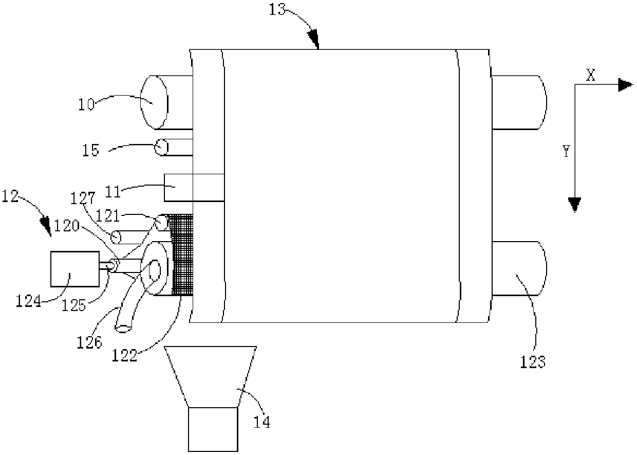
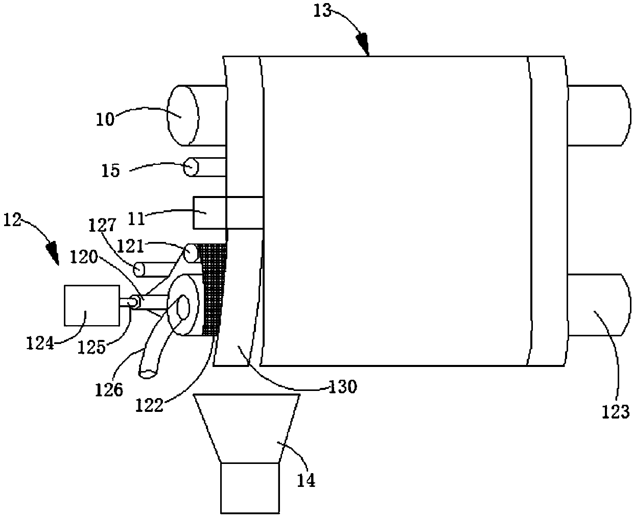
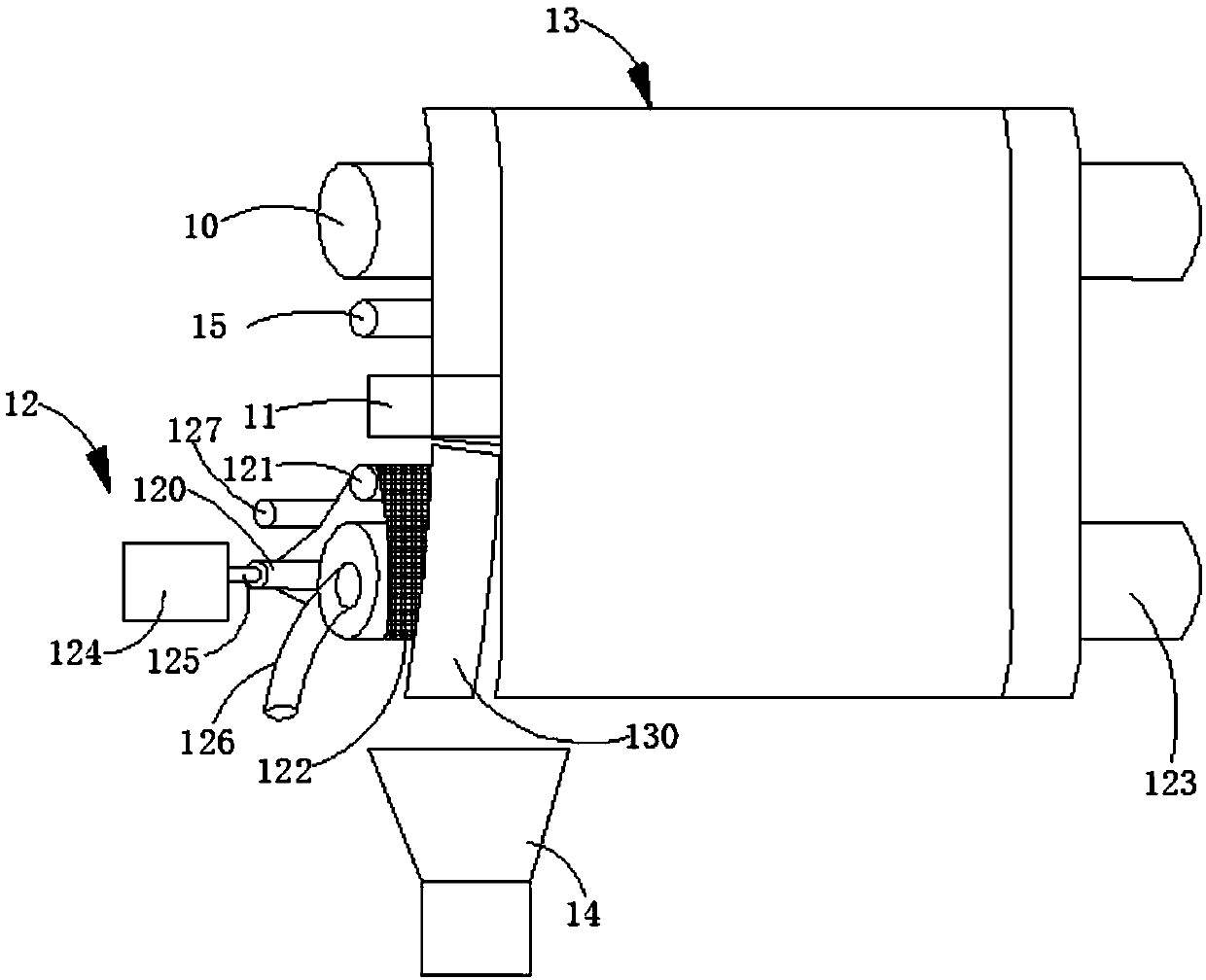
[0045] The embodiment of the present application provides a pole piece processing equipment, the pole piece processing equipment is used to process the pole piece 13, such as Figure 1 to Figure 3 As shown, the pole piece 13 can include an empty foil area and a coating area, the coating area is the position where the active material layer is coated on the pole piece 13, and the empty foil area is that the pole piece 13 is not coated with an active material The position of the layer, in the width direction of the pole piece 13 (such as figure 1 In the X direction shown in ), the empty foil area can be arranged on one side of the coating area, or on both sides of the coating area, or between adjacent coating areas.

[0046] The pole piece processing equipment may include a pole piece conveying mechanism 10 and a cutting mecha...


PUM


Abstract

The invention relates to the technical field of pole piece processing, in particular to pole piece processing equipment which comprises a pole piece conveying mechanism, a cutting mechanism and a waste adsorption mechanism. The pole piece conveying mechanism is arranged to convey a pole piece. The cutting mechanism is arranged to be opposite to the pole piece so as to cut the pole piece and form apole lug. The waste adsorption mechanism is arranged downstream of the cutting mechanism in the conveying direction of the pole piece. The waste adsorption mechanism comprises an active drive roller,a driven support roller and a conveying belt which is connected with the active drive roller and the driven support roller through transmission. The conveying belt is driven to rotate by the active drive roller and is arranged to provide suction force to the waste side to adsorb the waste side. According to the technical scheme, the shaking of the waste side which is not completely cut during thepole lug processing course can be effectively alleviated and the stability of subsequent cutting of the cutting mechanism can be improved.

Description

technical field [0001] The present application relates to the technical field of pole piece processing, in particular to a pole piece processing equipment. Background technique [0002] At present, in the pole piece processing process, the laser cutting mechanism is mainly used to cut the pole piece to form the tab, but when the laser cutting mechanism cuts out the tab and generates a waste edge, because the waste edge is not completely cut The front is still connected to the pole piece. During the transmission process of the pole piece, the edge of the waste that is not completely cut off will shake, which will easily cause the laser to defocus, reduce the cutting stability of the cutting mechanism, and thus reduce the stability of the pole piece. Cutting quality and forming quality of tabs. In addition, in order to minimize the vibration of waste materials, roll cutting is often used in the laser cutting process, and 5-8mm scraps are reserved on the pole piece, which will...

Claims


Application Information

Patent Timeline
IPC IPC(8): H01M4/04B23K26/38B23K26/70
CPCH01M4/04B23K26/38B23K26/702H01M4/8896H01M4/8878H01M4/0435H01M4/88H01M4/139H01M4/26Y02E60/50Y02E60/10H01L21/6838H01L29/401
Inventor 吴铁锋黄相强张涛廖能武仇少军杨玉怀
Owner CONTEMPORARY AMPEREX TECH CO
Features
  • R&D
  • Intellectual Property
  • Life Sciences
  • Materials
  • Tech Scout
  • Unparalleled Data Quality
  • Higher Quality Content
  • 60% Fewer Hallucinations
Learn More