
DC motor and rubber cover assembly thereof

A technology of DC motor and plastic cover, applied in the direction of electric components, electrical components, electromechanical devices, etc., can solve the problems of poor reliability, waste of labor cost, complicated production process, etc., achieve stable and reliable conductive connection, simplify assembly process, The effect of simplifying the internal structure

Pending Publication Date: 2019-12-10
厦门欣众达科技有限公司
View PDF1 Cites 1 Cited by
  • Summary
  • Abstract
  • Description
  • Claims
  • Application Information

AI Technical Summary

Problems solved by technology

[0003] The combination of the rubber cover and the circuit board, such as the rectifier bridge and the protector, are fixed on the circuit board by welding. There are many connecting lines, the structure is complicated, the manufacturing process is very complicated, and a lot of labor costs are wasted. , and the welding temperature is very high, the solder is easy to damage the components, especially the high temperature generated during the welding process will have an annealing effect on the spring on the rubber cover, resulting in weakened deformation of the spring, and the spring is used to drive the carbon brush, and then The carbon brush cannot be in good contact with the rotor, and the sparks become larger during operation, or even burn out
In addition, the plastic cover is provided with a storage box on the side, which takes up a lot of space
[0004] To sum up, the combination of the rubber cover and the circuit board of the existing motor has complex structure, complex production process, high production cost, and poor reliability

Method used


Image

  • DC motor and rubber cover assembly thereof
  • DC motor and rubber cover assembly thereof
  • DC motor and rubber cover assembly thereof

Examples


Embodiment Construction

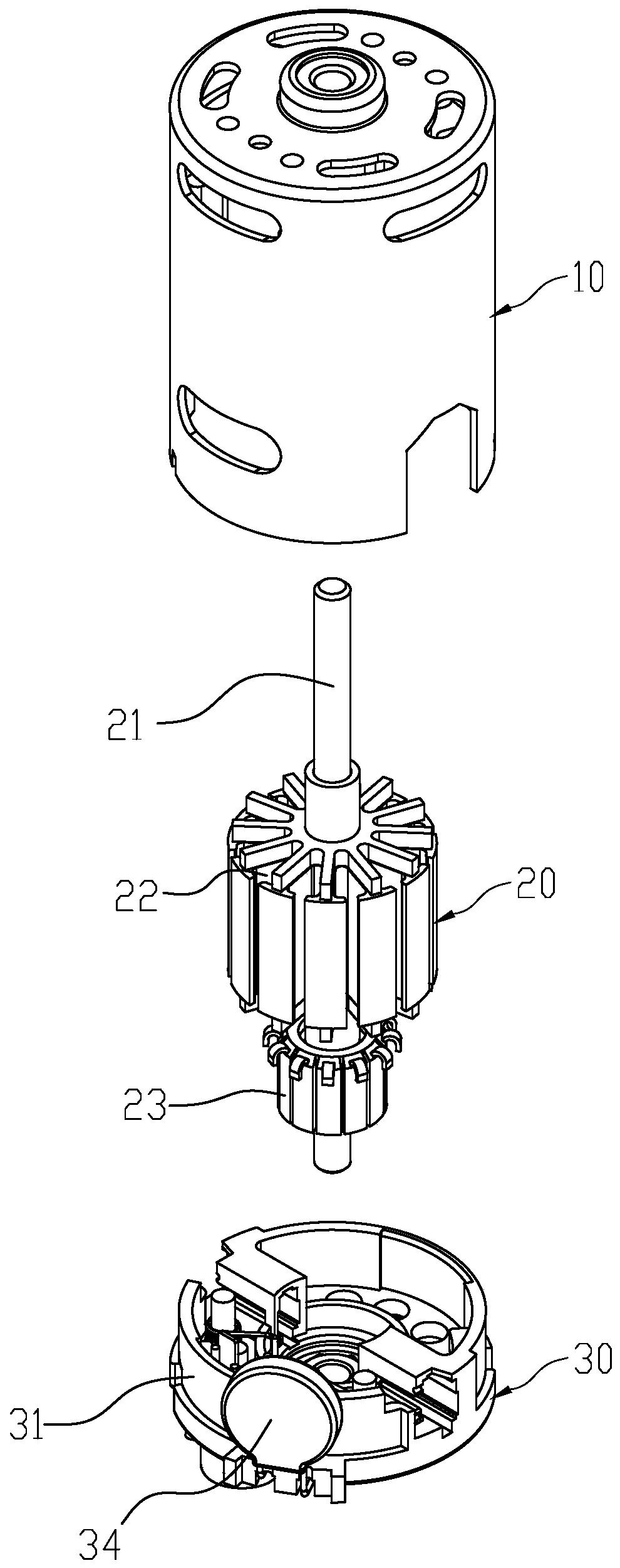
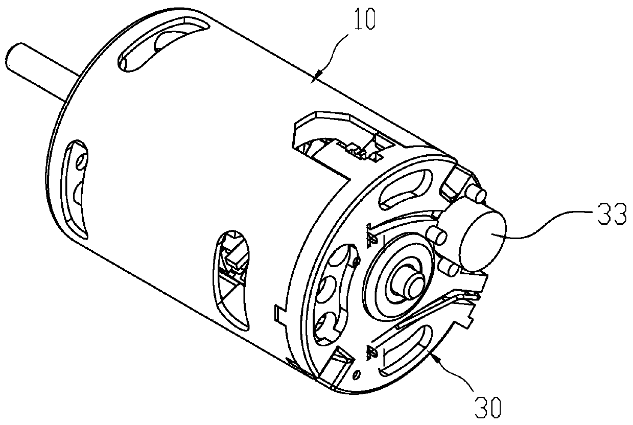
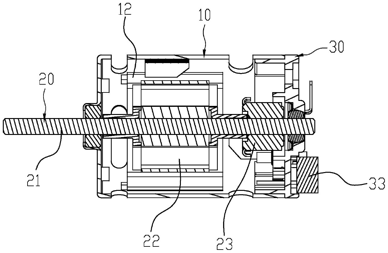
[0034] Please refer to Figure 1 to Figure 4 , a DC motor, including a stator 10, a rotor 20 and a rubber cover assembly 30. The stator 10 includes a housing 11 and a magnetic shoe 12 , one side of the housing 11 is open, and the magnetic shoe 12 is arranged in the housing 11 . The rotor 20 includes a shaft 21 , a coil 22 and a commutator 23 arranged on the shaft. The rotor 20 is rotatably arranged in the casing 11, the magnetic tile 12 just surrounds the outer side of the coil 22, and one end of the rotating shaft 12 protrudes from the end face on the other side of the casing 11, and the rubber cover assembly 30 covers the The open end surface of the housing 11 supports the other end of the rotating shaft 21 . The commutator 23 just corresponds to the inner cavity of the rubber cover assembly 30 , and the carbon brushes are arranged on the rubber cover assembly 30 and are in sliding contact with the commutator 23 . The operating circuit principle of the motor is existing k...


PUM


Abstract

The invention discloses a DC motor and a rubber cover assembly thereof. The rubber cover assembly comprises an insulated rubber cover main body, wherein two carbon brush chambers used for placing carbon brushes are arranged on an end face of an inner side of the rubber cover main body along the radial direction, the rubber cover assembly further comprises two torsional springs, a rectifier bridge,and a PPTC, the two torsional springs are respectively arranged corresponding to the carbon brushes in the two carbon brush chambers and are provided with a first pin and a second pin, the rectifierbridge is connected with an outer wall of the rubber cover main body and is provided with a first AC pin, a second AC pin, a positive electrode pin and a negative electrode pin, the positive electrodepin is electrically connected with the first pin of one torsion spring, the negative electrode pin is electrically connected with the first pin of the other torsion spring, the PPTC is connected withan outer wall of the rubber cover main body and is provided with an input pin and an output pin, and the output pin is electrically connected with the first AC pin. The rubber cover assembly is advantaged in that the pins of the rectifier bridge are directly and electrically connected with the pins of the torsion springs and the pins of the PPTC, the structure is simple, the manufacturing cost iseffectively saved, damage to elements caused by welding can be prevented, reliability of performance is guaranteed, and production efficiency is greatly improved.

Description

technical field [0001] The invention relates to a DC motor and its rubber cover assembly, in particular to a DC motor and its rubber cover assembly used on an air bed or an air mattress. Background technique [0002] Existing motors are equipped with rectifier bridges and PPTC protectors in order to obtain safe and reliable operation characteristics. The traditional connection methods of these electronic components are to solder them to circuit boards separately, and then install the circuit boards in rubber covers. For example, the utility model patent No. 201821238429.4 discloses a combination of a DC motor rubber cover and a circuit board. A storage box is arranged on the side of the storage box, and card slots are symmetrically provided on the two inner sides of the storage box. [0003] The combination of the rubber cover and the circuit board, such as the rectifier bridge and the protector, are fixed on the circuit board by welding. There are many connecting lines, th...

Claims


Application Information

Patent Timeline
Patent Type & Authority Applications(China)
IPC IPC(8): H02K5/14H02K11/04H02K11/05H02K11/20
CPCH02K11/044H02K5/145H02K11/05H02K11/20
Inventor 陈校伟韩丽
Owner 厦门欣众达科技有限公司
Learn More