CAN FD bus automatic control system and method based on hardware logic

A technology of automatic control and hardware logic, applied in the field of communication, it can solve the problems of sending messages that cannot guarantee accurate time, the controlled node cannot respond in time, and unpredictable delay, etc., and achieves strong text editing and display capabilities. , the effect of eliminating the control data transmission delay, the effect of eliminating the delay

Inactive Publication Date: 2019-12-10
上海千顾汽车科技有限公司
View PDF0 Cites 1 Cited by
  • Summary
  • Abstract
  • Description
  • Claims
  • Application Information

AI Technical Summary

Problems solved by technology

[0005] 1. The upper computer is a non-real-time system, and there is an unpredictable delay in the system, so that the precise time of message sending, receiving and timing functions cannot be guaranteed;
[0006] 2. Connect the computer to the CAN FD bus through a specific CAN FD conversion interface, so that an event on the CAN FD bus is transmitted to the host

Method used


Image

  • CAN FD bus automatic control system and method based on hardware logic
  • CAN FD bus automatic control system and method based on hardware logic
  • CAN FD bus automatic control system and method based on hardware logic

Examples


Embodiment Construction

[0029] In order to make the objectives, technical solutions and advantages of the present invention clearer, the present invention will be further described in detail below in conjunction with specific examples and with reference to the accompanying drawings. It should be understood that these descriptions are only exemplary and not intended to limit the scope of the present invention. In addition, in the following description, descriptions of well-known structures and technologies are omitted to avoid unnecessarily obscuring the concept of the present invention.

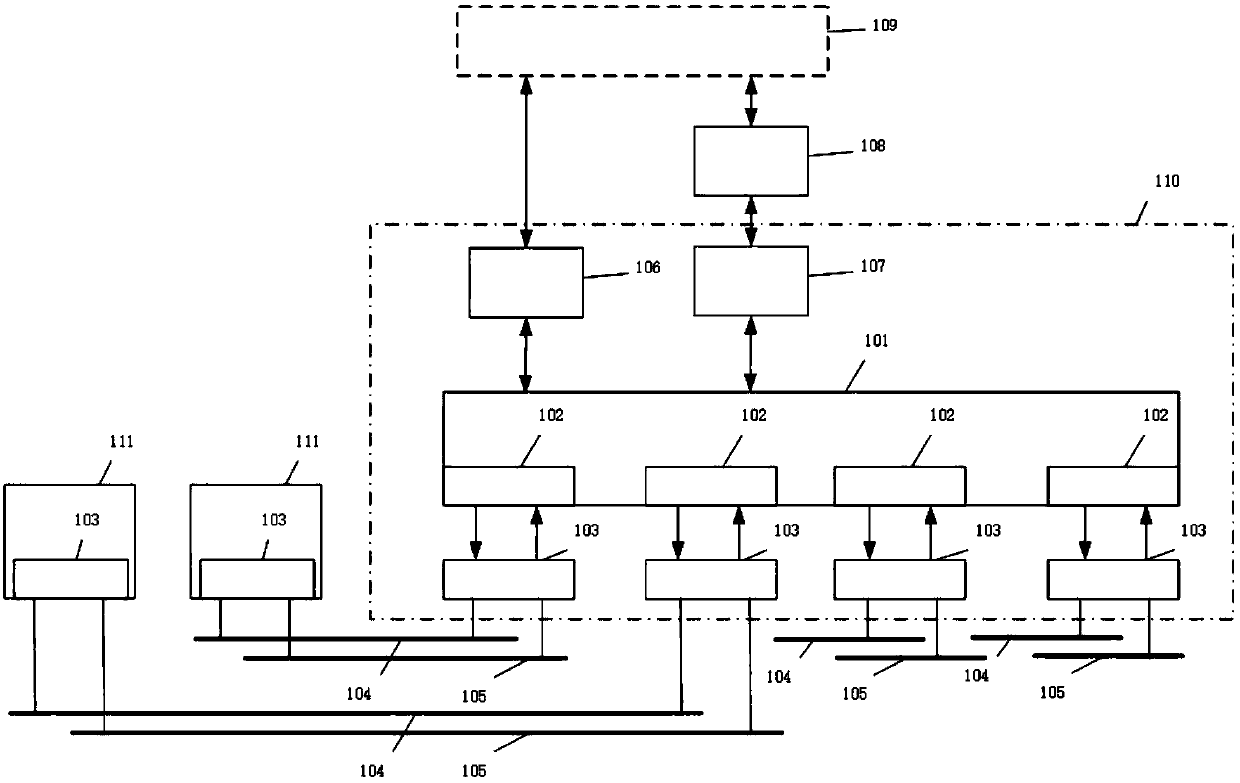
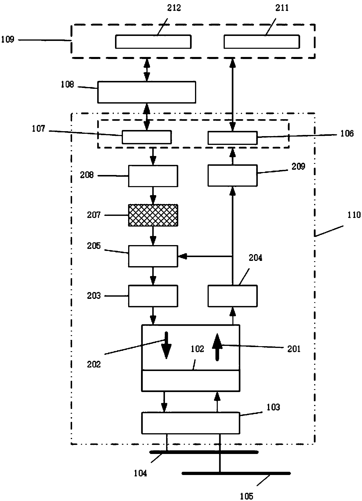
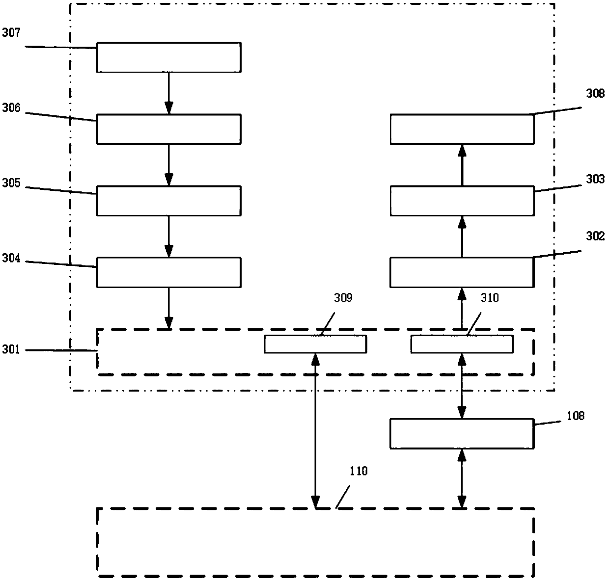
[0030] In order to overcome the shortcomings of real-time performance and high cost of the automatic test of CAN FD bus based on PC, the present invention provides a solution for hardware execution of automatic control scripts, thereby eliminating the non-real-time performance and transmission delay of the upper computer. The impact of this has improved the control accuracy and reduced the cost of the control system.

...


PUM


Abstract

The invention discloses a CAN FD bus automatic control system and method based on hardware logic. The CAN FD bus automatic control system comprises an upper PC and a lower computer hardware circuit. The lower computer hardware circuit comprises a microcontroller, a Bluetooth module, a USB3.1 module and a CAN FD transceiver; the lower computer hardware circuit is wirelessly connected to the PC through a USB3.1 cable or Bluetooth, and the lower computer hardware circuit is connected and communicated with the controlled node through a CAN FD bus CANH and a CAN FD bus CANL at the same time; the microcontroller is connected with at least four CAN FD controllers; a TX pin and an RX pin of each CAN FD controller are respectively connected with a TX pin and an RX pin of the CAN FD transceiver; theCANH of the CAN FD transceiver is connected to the CAN FD bus CANH, and the CANL of the CAN FD transceiver is connected to the CAN FD bus CANL. According to the invention, the non-real-time performance of the upper computer and the influence caused by transmission delay are eliminated, the control precision is improved, and the cost of the control system is reduced.

Description

Technical field [0001] The present invention relates to the field of communication technology, in particular to a CAN FD bus automation control system and method based on hardware logic. Background technique [0002] CAN FD bus, as the communication interface between the emerging microcontrollers, is gradually popularized in automobiles and industries. With the increasing complexity of the internal program of each microcontroller based on the CAN FD bus, the difficulty of its automation control is getting higher and higher. [0003] Based on CAN FD bus to automatically control the electronic control unit under test, the usual way is to write a special control program for the items of control requirements, and through the corresponding interface (such as USB to CAN FD bus device), the report needs to be sent The text is sent to the bus connected to the controlled node, and the response of the controlled node is read from the bus at the same time, so that the host computer monitors ...

Claims


Application Information

Patent Timeline
IPC IPC(8): H04L12/40H04L29/08H04W4/80
CPCH04L12/40H04W4/80H04L12/40013H04L2012/40215H04L67/568
Inventor 刘矗郁立华
Owner 上海千顾汽车科技有限公司
Why Eureka
Try Eureka