CT scanner defocusing radiation intensity distribution measurement method

A radiation intensity and measurement method technology, which is applied in the fields of radiological diagnostic instruments, medical science, and diagnosis, can solve problems such as inaccurate calculation and influence of measurement results, and achieve accurate calculation results, simple and stable calculation process, and scan saving The effect of times

Active Publication Date: 2019-12-13
FMI MEDICAL SYST CO LTD
View PDF13 Cites 5 Cited by
  • Summary
  • Abstract
  • Description
  • Claims
  • Application Information

AI Technical Summary

Problems solved by technology

This method has high requirements on the phantom, if the attenuation of the phantom is not high enough or thin enough, it may make the calculation inaccurate
In addition, detector gain calibration is usually required before scanning a large phantom. The measurement of the defocused radiation intensity distribution needs to be very precise, and a slight deviation of the detector gain will have a great impact on the measurement results.

Method used


Image

  • CT scanner defocusing radiation intensity distribution measurement method
  • CT scanner defocusing radiation intensity distribution measurement method
  • CT scanner defocusing radiation intensity distribution measurement method

Examples


Embodiment Construction

[0038] In order to make the technical means of the present invention and the technical effects that can be achieved more clearly and more completely disclosed, an embodiment is provided hereby, and the following detailed description is given in conjunction with the accompanying drawings:

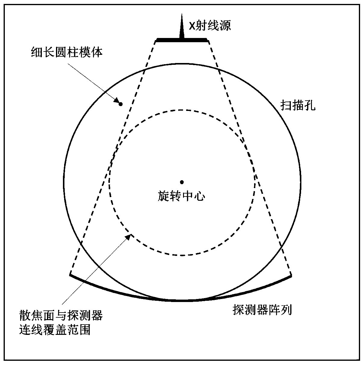
[0039] Such as figure 1 As shown, a slender cylindrical phantom is fixed in the scanning aperture, perpendicular to the scanning plane, and placed outside the coverage of the line connecting the defocus plane and the detector, so that the ray source and detector array rotate around the center of rotation (if a ray The source and the detector are the reference system, which is equivalent to the phantom rotating around the rotation center) and the phantom can cut the connection line between any point on the defocus surface and any detector unit.

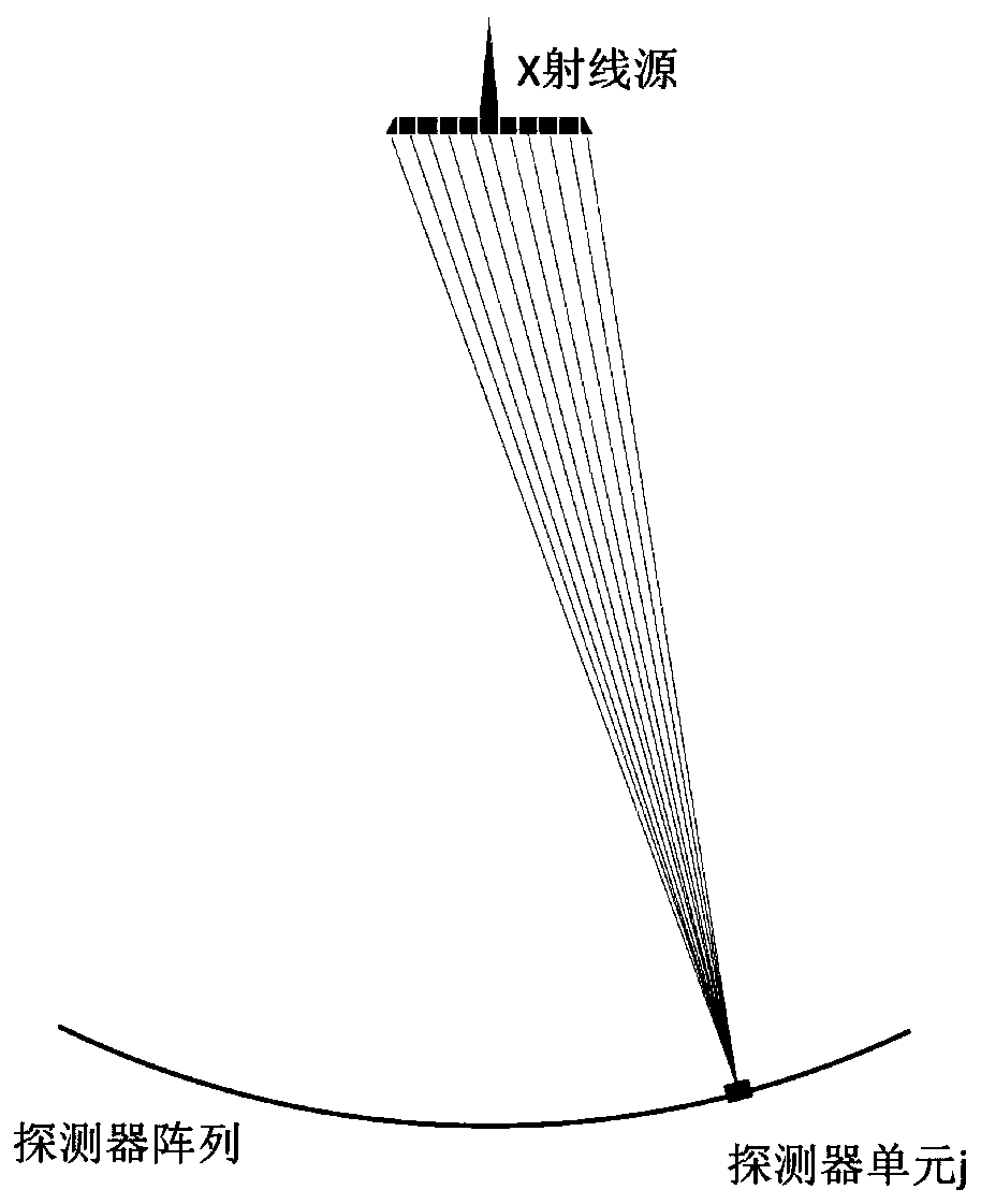
[0040] Rotate the gantry and perform an exposure scan. During this process, the phantom will cut the connection line between any point on the defocu...


PUM


Abstract

The invention provides a CT scanner defocusing radiation intensity distribution measurement method, and relates to the technical field of CT data correction methods. The method comprises the steps: enabling a slender cylindrical die body to be fixed in a scanning aperture, to be perpendicular to a scanning plane, and to be far away from a rotation center as much as possible; enabling an X-ray source and a detector of a scanner to continuously rotate around the rotation center of a rack and executing exposure and data acquisition; carrying out background removal on the collected data; extracting signals which are not shielded at all, calculating an empty scanning gain of each detector unit, and carrying out gain correction on all data; and for each detector unit, calculating a sampling point through which a connecting line of a defocusing surface and the detector passes, and calculating the intensity of the sampling point reaching the detector units according to the attenuation value ofthe sampling point relative to the attenuation value when the sampling point is not shielded, and thus obtaining final defocusing distribution. According to the method provided by the invention, theintensity distribution of the defocusing radiation is obtained through the actual measurement of the specific die body, and more accurate correction can be carried out for the difference of each system.

Description

technical field [0001] The invention relates to a method for correcting CT data, in particular to a method for measuring the distribution of defocused radiation intensity of a CT scanner. Background technique [0002] Computed tomography (computed tomography, CT) is a device that uses X-ray rotation to irradiate the object to be measured, and then obtains a tomographic image of the object through computer processing. In CT, X-rays are usually obtained by bombarding the anode target with an electron beam. The ideal X-ray source should be a point, but after the electron beam bombards the focal area of ​​the anode target, some electrons will be scattered and sputtered and bombard the anode target again. produce a small amount of X-rays. Rays outside the focal point will cause blurred edges of objects in the reconstructed image, which may affect the doctor's diagnosis in severe cases. [0003] Therefore, in order to solve the above problems, the following methods are adopted i...

Claims


Application Information

Patent Timeline
IPC IPC(8): A61B6/00
CPCA61B6/583A61B6/585
Inventor 黄俊杰王瑶法刘健宏王斌
Owner FMI MEDICAL SYST CO LTD
Why Eureka
Try Eureka