Ultrasonic receiving transducer based on Helmholtz resonant cavity

An ultrasonic transducer, resonant cavity technology, applied in the direction of the fluid using vibration, can solve the problems such as the decrease of the quality factor Q and the increase of the cavity resonant frequency, and achieve the advantages of increasing the sensitivity, reducing the energy loss and increasing the acousto-electrical conversion efficiency. Effect

Active Publication Date: 2019-12-13
武汉敏声新技术有限公司
View PDF11 Cites 14 Cited by
  • Summary
  • Abstract
  • Description
  • Claims
  • Application Information

AI Technical Summary

Problems solved by technology

When the fingerprint is pressed on the cavity, the resonance frequency of the cavity will increase and the quality factor Q will decrease.

Method used


Image

  • Ultrasonic receiving transducer based on Helmholtz resonant cavity
  • Ultrasonic receiving transducer based on Helmholtz resonant cavity
  • Ultrasonic receiving transducer based on Helmholtz resonant cavity

Examples


Embodiment Construction

[0029] The invention will be further described below in conjunction with the accompanying drawings and specific embodiments.

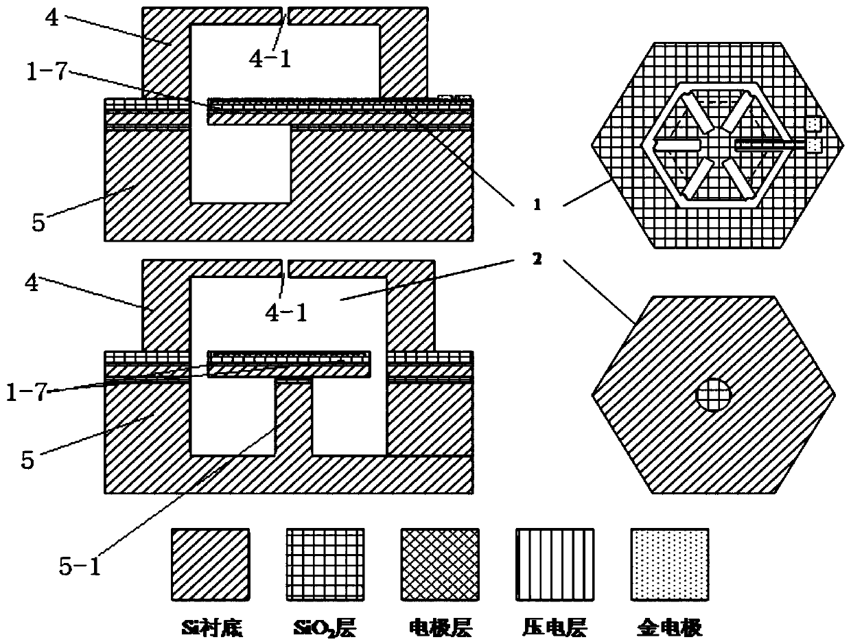
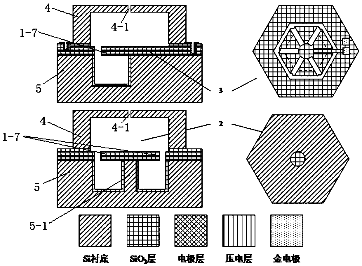
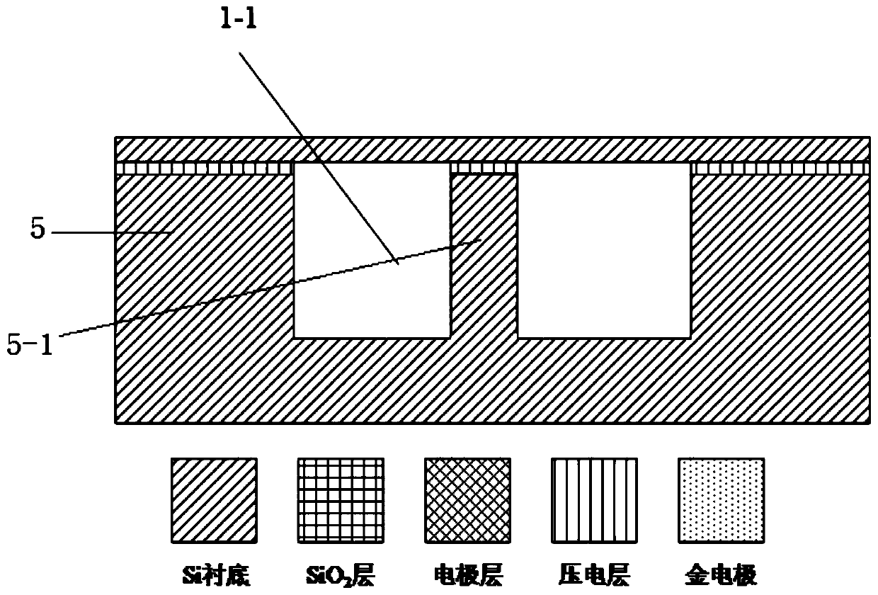
[0030] Such as figure 1 , 2 , a receiving ultrasonic transducer based on a Helmholtz resonant cavity, including a Helmholtz resonant cavity 2 and a MEMS piezoelectric ultrasonic transducer combined by bonding. The MEMS piezoelectric ultrasonic transducer is composed of an upper piezoelectric laminated structure and a silicon substrate 5 with a cavity at the bottom, and the middle part of the structure of the silicon substrate 5 with a cavity at the bottom is etched to form a raised silicon substrate The pillar 5-1, the silicon substrate pillar 5-1 plays a role of supporting the piezoelectric stack structure.

[0031] The Helmholtz resonant cavity 2 is composed of a cavity silicon structure 4 with an upper opening 4-1 above the piezoelectric stack structure. The cavity silicon structure 4 is a semi-enclosed structure, and the opening is downward and t...


PUM


Abstract

The invention discloses an ultrasonic receiving transducer based on a Helmholtz resonant cavity. The ultrasonic receiving transducer based on the Helmholtz resonant cavity comprises the Helmholtz resonant cavity and an MEMS piezoelectric ultrasonic transducer which are combined through bonding, wherein the MEMS piezoelectric ultrasonic transducer is composed of a piezoelectric laminated structureand a silicon substrate with a cavity body, the Helmholtz resonant cavity is composed of a silicon structure with a cavity body and an upper opening, the silicon structure is located above the piezoelectric laminated structure, a Helmholtz resonant cavity hole is formed in the upper opening, and air in the Helmholtz resonant cavity hole forms an air column of the Helmholtz resonant cavity; the middle part of the silicon substrate structure with the cavity body and at the bottom is etched to form a bulged silicon substrate strut, an annular groove is etched in the piezoelectric laminated structure around the silicon substrate strut, a plurality of radial grooves are etched in the piezoelectric laminated structure by taking the silicon substrate strut as a center, and the piezoelectric laminated structure is partitioned into a plurality of fan-shaped structures or a plurality of trapezoidal structures; and the plurality of fan-shaped structures or the plurality of trapezoidal structuresform a cantilever beam, one end, making contact with the silicon substrate strut, of the cantilever beam, forms a fixed end, and one end, away from the silicon substrate strut, of the cantilever beam,forms a free end. The performance of the ultrasonic receiving transducer can be improved.

Description

technical field [0001] The invention belongs to the technical field of MEMS ultrasonic transducers, and relates to a receiving ultrasonic transducer based on a Helmholtz resonant cavity. Background technique [0002] An ultrasonic transducer is a transducing element that can be used to both transmit and receive ultrasonic waves. When working in the transmitting mode, the electric energy is converted into the vibration of the transducer through electrostatic force or inverse piezoelectric effect to radiate sound waves; when working in the receiving mode, the sound pressure acts on the surface of the transducer to vibrate, and the transducer The vibration is then converted into an electrical signal. At present, the most widely used ultrasonic sensors are mainly based on bulk piezoelectric transducers, which mainly use the thickness vibration mode of piezoelectric ceramics to generate ultrasonic waves. Since the resonance frequency of the thickness mode is only related to the ...

Claims


Application Information

Patent Timeline
Patent Type & Authority Applications(China)
IPC IPC(8): B06B1/06
CPCB06B1/06B06B2201/55
Inventor 孙成亮吴志鹏胡博豪王磊朱伟林炳辉周禹
Owner 武汉敏声新技术有限公司
Why Eureka
Try Eureka