Reinforcing steel bar bending structure, reinforcing steel bar bending device and reinforcing steel bar bending method

A technology for bending and reinforcing steel bars, applied in the field of construction equipment, can solve the problems of time-consuming and laborious, the two ends of the steel bars are warped, the reinforcement process, and the complicated process.

Inactive Publication Date: 2019-12-13
CHONGQING ZHONGKE CONSTR GROUP
View PDF15 Cites 3 Cited by
  • Summary
  • Abstract
  • Description
  • Claims
  • Application Information

AI Technical Summary

Problems solved by technology

There are two existing adjustment methods. One is to cut the steel bar and reinforce at the cut position of the steel bar at the same time. The reinforcement work is mainly to carry out support reinforcement or welding reinforcement within the range of the cut steel bar. The reinforcement process and process are complicated and time-consuming The second is to bend the steel bar by the steel bar bending machine, but due to the influence of the force on the steel bar, the two ends of the steel bar will warp in the opposite direction of the force, which will drive the deformation of the steel bar grid near the steel bar. The deformed steel bar mesh is as follows: figure 2 shown

Method used


Image

  • Reinforcing steel bar bending structure, reinforcing steel bar bending device and reinforcing steel bar bending method
  • Reinforcing steel bar bending structure, reinforcing steel bar bending device and reinforcing steel bar bending method
  • Reinforcing steel bar bending structure, reinforcing steel bar bending device and reinforcing steel bar bending method

Examples


Embodiment 1

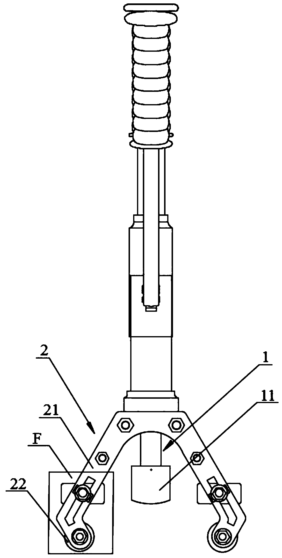
[0040] Such as Figure 3 to Figure 7 As shown, a steel bending structure includes a push rod 1 and a support frame 2. The support frame 2 includes two fixed arms 21, and the push rod 1 passes through the support frame 2 and is located between the two fixed arms 21;

[0041] A pulley 22 is provided at the end of the fixed arm 21, and a pressing block 23 is also provided on the fixed arm 21 corresponding to the pulley 22. A steel bar passing hole is reserved between the pulley 22 and the pressing block 23. Preferably, the pressing block is a square block, and the pulley is a grooved round pulley, which is beneficial to increase the force-bearing area at both ends of the steel bar and further improve the bending quality of the steel bar.

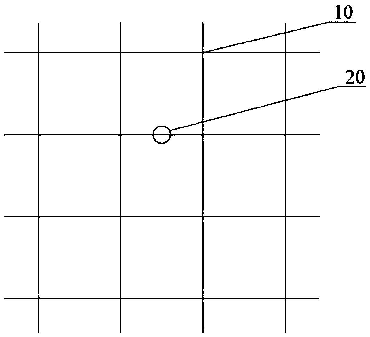
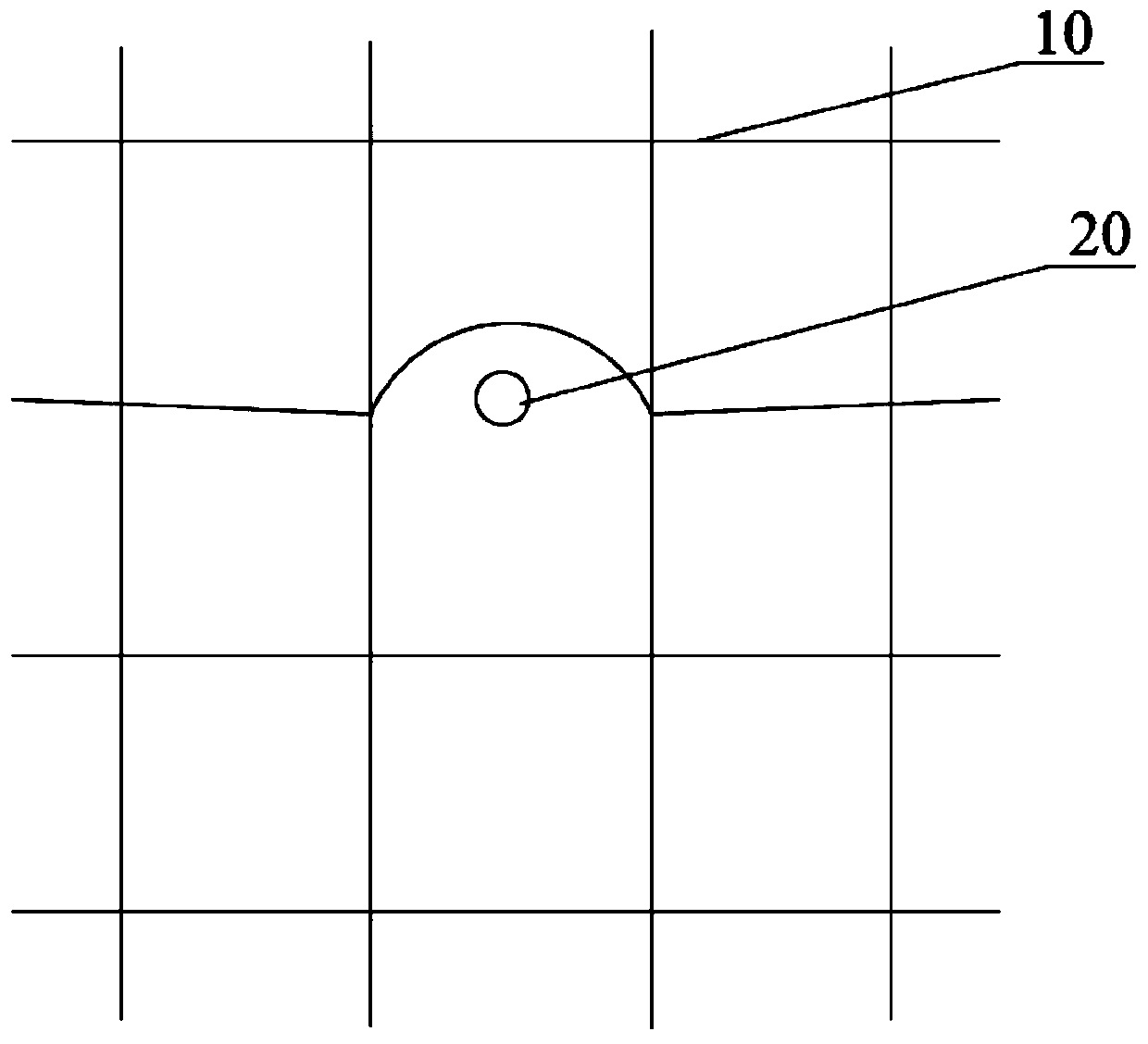
[0042] After pressing the steel bar on the bending structure of the steel bar, push the push rod to make the push rod act in the middle of the steel bar. Since the two ends of the steel bar are pressed by the pressure block, the two ends of the stee...

Embodiment 2

[0049] A steel bar bender includes the steel bar bending structure of Embodiment 1. The steel bar bender also includes a piston rod, an air cylinder, and an air intake pump. One end of the piston rod is connected to the push rod, and the other end is connected to the air cylinder through a spring. The air hole, the air inlet pump is connected with the air hole through the air pipe.

[0050] When used, it is basically the same as that of Embodiment 1, except that the push rod of this embodiment is pushed out by air pressure.

Embodiment 3

[0052] The structure of the third embodiment is basically the same as that of the second embodiment. The difference is that this embodiment replaces the intake pump in the second embodiment with a hydraulic pump. The piston rod and the hydraulic pump are both set in the cylinder, and one end of the piston rod is connected with the push rod. The other end is connected with the hydraulic pump, and the hydraulic pump is connected with the motor. In this embodiment, the push rod is pushed out hydraulically.


PUM


Abstract

The invention discloses a reinforcing steel bar bending structure. The reinforcing steel bar bending structure comprises a pushing rod and a supporting frame; the supporting frame comprises two fixingarms; the pushing rod penetrates through the supporting frame and is located between the two fixing arms; sliding wheels are arranged at the ends of the fixing arms; and pressing blocks correspondingto the sliding wheels are further arranged on the fixing arms. Besides, the invention further relates to a reinforcing steel bar bending device utilizing the reinforcing steel bar bending structure and a reinforcing steel bar bending method. The reinforcing steel bar bending structure, the reinforcing steel bar bending device and the reinforcing steel bar bending method have the beneficial effects that through cooperation of the pressing blocks and the sliding wheels, under the action force of the pushing rod, two ends of a reinforcing steel bar are pressed by the pressing blocks, thus the two ends are kept horizontal all the time, and the condition that the strength of a reinforcing steel bar mesh is affected due to the fact that the two ends of the reinforcing steel bar are deformed byforce to pull the adjacent reinforcing steel bar mesh is avoided; and besides, the pressing blocks can slide on the fixing arms, so that reinforcing steel bars in different diameters can be bent by the structure, and the applicability is improved.

Description

Technical field [0001] The invention relates to the field of building construction equipment, in particular to a steel bar bending structure, a steel bar bender and a steel bar bending method. Background technique [0002] When pre-buried pipelines for the production of prefabricated components and water and electricity installations of housing construction projects are reserved for pre-buried, for the installation of electrical light boxes, water supply and drainage pipes and other hydropower pre-embedded parts, it is necessary to locate the pre-buried in strict accordance with the design and construction drawings; However, the actual design drawing does not ensure that all embedded parts are located in the mesh of the steel mesh. Such as figure 1 As shown, the position of the embedded part 20 just falls on the steel bars of the steel mesh 10; in actual construction, it is often encountered that this kind of embedded part conflicts with the position of the steel mesh; at this ti...

Claims


Application Information

Patent Timeline
Patent Type & Authority Applications(China)
IPC IPC(8): B21F1/00E04C5/04
CPCB21F1/004E04C5/04
Inventor 刘耶霖肖大海王克君
Owner CHONGQING ZHONGKE CONSTR GROUP
Why Eureka
Try Eureka