
Electric discharge machining jig and method

A technology of electrical discharge machining and fixtures, which is applied in the field of mold processing, can solve problems such as unsynchronized tightening of screws, abnormal mold quality, and tilting of copper males, etc., to save time for calibration, ensure processing quality, and avoid processing errors.

Pending Publication Date: 2019-12-13
GREE ELECTRIC APPLIANCES WUHAN +1
View PDF0 Cites 1 Cited by
  • Summary
  • Abstract
  • Description
  • Claims
  • Application Information

AI Technical Summary

Problems solved by technology

There are two screws to fix and adjust the direction of the chuck for loading copper or electrodes on the spark machine, and the two screws cannot be tightened synchronously. The copper or electrodes will tilt under the stress of the two screws successively, resulting in The Z-axis direction is not vertical. At the same time, when the two screws are manually tightened, the tightening force is often not guaranteed to be the same, which will also cause the copper male to tilt, and eventually lead to EDM quality problems.
[0004] In addition, even if the copper male is aligned, it is still necessary for the copper male to touch the origin of the mold for electrical discharge machining. Repeated calibration and adjustment of the copper male or electrode not only wastes man-hours, but also easily causes the mold to be discharged due to unaligned conditions. Abnormal quality and other issues
Therefore, the existing processing mode leads to high work intensity of the processing master, and also restricts the effective working time of the spark machine

Method used


Image

  • Electric discharge machining jig and method
  • Electric discharge machining jig and method
  • Electric discharge machining jig and method

Examples


Embodiment Construction

[0036] The present invention will be further described below in conjunction with accompanying drawing.

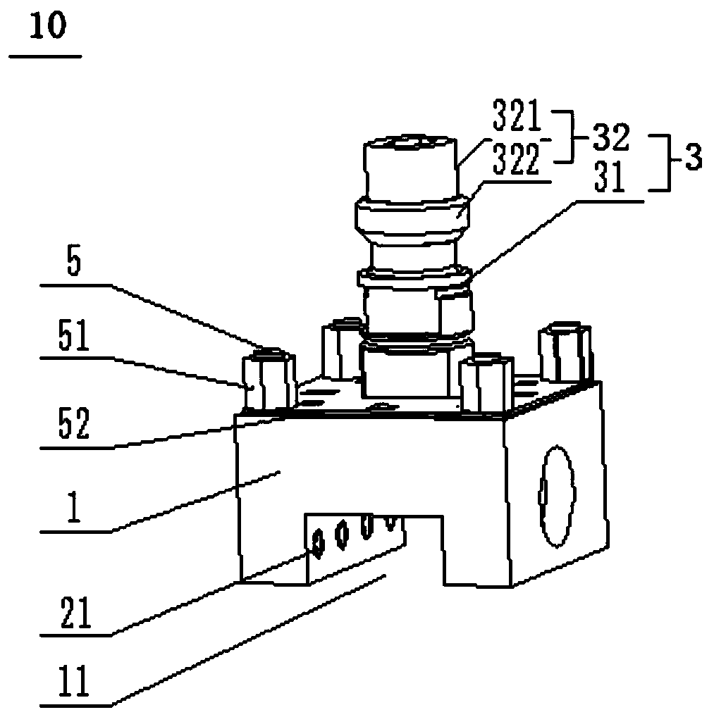
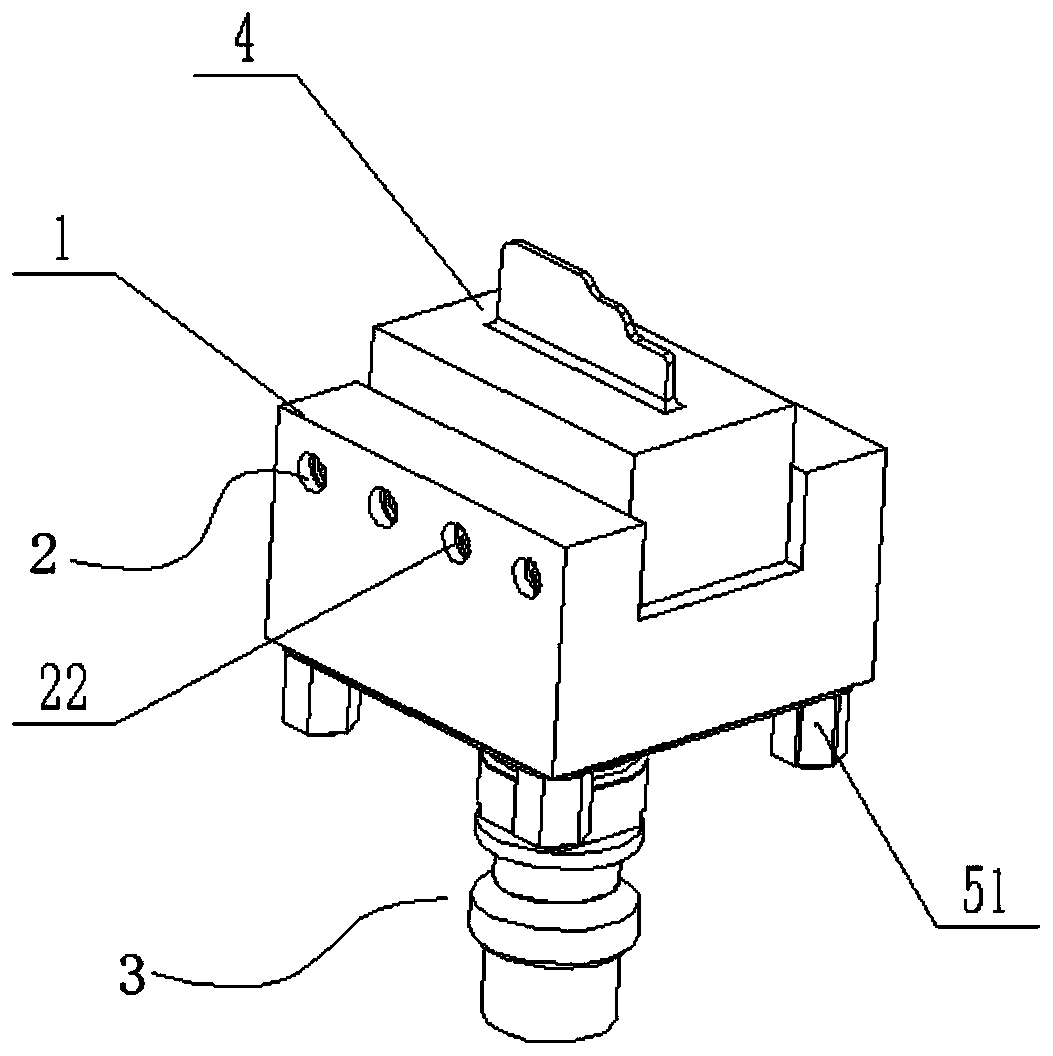
[0037] figure 1 shows a schematic structural view of an electrical discharge machining fixture according to the present application, figure 2 shown figure 1 Schematic diagram of the structure of the electric discharge machining fixture after the electrode is installed.

[0038] refer to figure 1 and figure 2 , the electrical discharge machining fixture 10 includes a fixture main body 1 , a positioning component 2 and a fixing component 3 .

[0039] The top of the fixture main body 1 has a groove 11 for accommodating the electrode 4, and the electrode 4 may be a graphite electrode or a copper male electrode. The positioning component 2 is arranged on the side wall of the fixture body 1 for fixing the electrode 4 . The fixing assembly 3 includes a fixing handle 31 and a connecting piece 32. The fixing handle 31 is arranged on the bottom surface of the fixture main bod...


PUM


Abstract

The invention provides an electric discharge machining jig which includes a jig body, a positioning assembly and a fixing assembly. The top of the jig body is provided with a groove, and the groove isused for accommodating an electrode; the positioning assembly is arranged at the position near the groove and is used for fixing the electrode; and the fixing assembly includes a fixing handle and aconnecting member, the fixing handle is arranged on the bottom surface of the jig body and located at the center position of the bottom surface of the jig body, and the connecting member is used for mounting the fixing handle to electric discharge machining equipment and electrode processing equipment. According to the electric discharge machining jig, the fixing assembly is arranged at the centerposition of the bottom surface of the jig body, after the electrode is fixed to the jig body, the electrode and the jig body can be integrated to be mounted to the electrical discharge machining jigthrough the fixing assembly, and the step of calibrating the electrode is eliminated.

Description

technical field [0001] The invention relates to the technical field of mold processing, and more specifically, to an electrical discharge machining fixture and method. Background technique [0002] With the development of the mold industry, the requirements for the precision and complexity of the mold are getting higher and higher, and at the same time, more stringent requirements are put forward for the processing cycle of the mold. [0003] In the actual processing of molds, the processes with relatively long processing time and relatively low efficiency are mainly concentrated in the EDM process. EDM is mainly aimed at workpieces that cannot be processed by other processing methods in the machining center. The processing positions are generally narrow and deep positions such as ribs and columns, and require high machining accuracy. However, a part on the mold often requires multiple copper males or electrodes to complete the processing, and each copper male or electrode ...

Claims


Application Information

Patent Timeline
IPC IPC(8): B23H11/00B23H1/00
CPCB23H11/003B23H1/00
Inventor 李超张占华
Owner GREE ELECTRIC APPLIANCES WUHAN
Features
  • Generate Ideas
  • Intellectual Property
  • Life Sciences
  • Materials
  • Tech Scout
  • Unparalleled Data Quality
  • Higher Quality Content
  • 60% Fewer Hallucinations
Learn More