Scrap cutter edge surface machining method

A processing method and cutting edge cutting technology, which are applied in the field of cutting edge cutting edge surface processing, can solve the problems of low production efficiency and poor processing precision of cutting edge cutting edge surface, so as to improve the precision, improve the cutting edge effect, and improve the overall Efficient effect

Active Publication Date: 2019-12-13
ANHUI LINGFENG METALLURGICAL MACHINERY
View PDF7 Cites 0 Cited by
  • Summary
  • Abstract
  • Description
  • Claims
  • Application Information

AI Technical Summary

Problems solved by technology

[0006] Aiming at the problems of poor machining accuracy and low production efficiency of the existing chipping shears, the present invention provides a processing method for the chipping shears, in which the edge surface of the chippings to be processed is processed by turning, milling and grinding. Process

Method used


Image

  • Scrap cutter edge surface machining method
  • Scrap cutter edge surface machining method
  • Scrap cutter edge surface machining method

Examples


Embodiment 1

[0092] A method for processing the edge surface of a chipped cutting edge, the steps are as follows:

[0093] 1. Turning: install the cutting edge to be processed on the turning and grinding fixture and then assemble it into the lathe, and the lathe performs rough turning on the cutting edge surface 103 to be processed;

[0094] 2. Milling: install the chipped edge cutting edge after rough turning in step 1 on the milling fixture and then assemble it into the milling machine, and the milling machine performs milling processing on the chipped edge cutting edge surface 103;

[0095] 3. Grinding: install the chipped edge after milling in step 2 on the turning and grinding fixture, and then assemble it into the grinding machine, and the grinder performs fine grinding on the chipped edge surface 103 .

[0096] like Figure 20 As shown, in the method for processing the surface of the chipping and cutting edge in this embodiment, the surface of the chipping and cutting edge is rough...

Embodiment 2

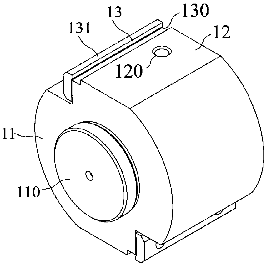
[0099] like figure 1 and Image 6 As shown, a method for processing the cutting edge and cutting edge surface of the present embodiment is further improved on the basis of embodiment 1, and the described turning and grinding fixture includes:

[0100] matrix 11, which is a columnar body;

[0101] An assembly platform 110, which is arranged at the center of an end surface of the base body 11, is used for assembling the fixture on the machine tool;

[0102] The installation surface 12 is a plane arranged on the side of the base body 11, and the installation surface 12 is horizontal to the central axis of the base body 11;

[0103] Mounting hole 120, which is formed on the mounting surface 12, is shaped to match the mounting hole 102 of the trimmer;

[0104] A concave structure 13 is formed on one side of the installation surface 12 along the central axis of the base body 11, and is used for placing the lower convex eaves 101 of the cutting edge.

[0105] During the processin...

Embodiment 3

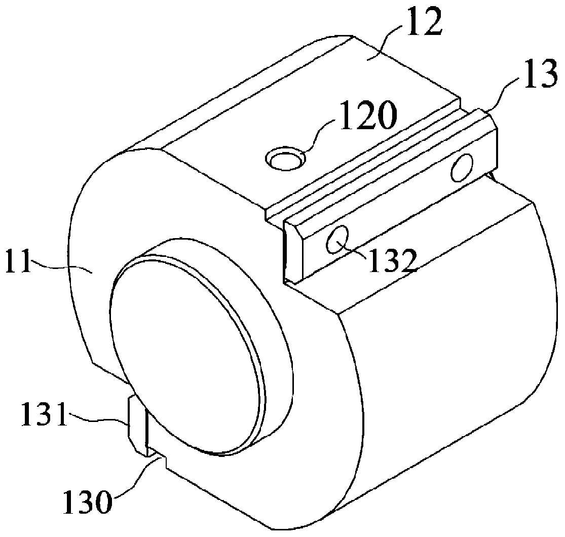
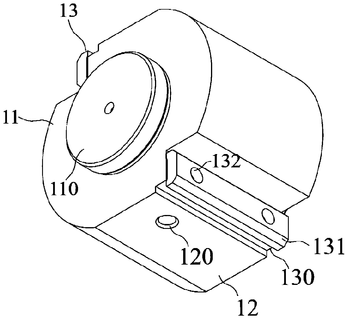
[0112] like figure 1 , figure 2 , image 3 , Figure 4 and Figure 11 As shown, a method for processing the cutting edge and cutting edge surface of this embodiment is further improved on the basis of Embodiment 2. The concave structure 113 of the turning and grinding fixture includes:

[0113] A concave step 130, which is arranged axially along the center of the base body 11, is in the shape of a two-step concave step, and is set on the side of the installation surface 12;

[0114] Fastening plate 131, which is detachably connected to the secondary vertical surface 1302 of the concave step 130;

[0115] The fastening plate 131 and the first horizontal surface 1300 and the first vertical surface 1301 of the concave step 130 form a groove structure.

[0116] The concave structure 13 can be a variety of structures, such as the groove directly opened on one side of the mounting surface 12, but there are certain defects in the directly opened groove structure. The amount of...


PUM


Abstract

The invention discloses a scrap cutter edge surface machining method, and belongs to the field of scrap cutter edge machining. The scrap cutter edge surface machining method comprises the following steps: (1) turning: scrap cutter edges to be machined are assembled in a lathe after installation on a turning and grinding fixture; and scrap cutter edge surfaces to be machined are roughly turned by the lathe; (2) milling: the scrap cutter edges roughly turned in the step (1) are assembled in a milling machine after installation on a milling fixture; and the scrap cutter edge surfaces are milled by the milling machine; and (3) grinding: the scrap cutter edges milled in the step (2) are assembled into a grinding machine after installation on the turning and grinding fixture; and the scrap cutter edge surfaces are finely grinded by the grinding machine. The edge surfaces of the scrap cutter edges to be machined are machined through the turning, milling and grinding steps, and all the steps can be performed at the same time, so that the machining method achieves higher overall efficiency; and through each step machining, the precision of the scrap cutter edge surfaces is continuously improved, and the scrap cutting effect and the service life of the scrap cutter edges are improved.

Description

technical field [0001] The invention belongs to the field of chipping and cutting edge processing, and more specifically relates to a cutting edge cutting edge processing method. Background technique [0002] Shredding shears are commonly used equipment in material processing. They are used to cut the edge of materials to ensure the quality of the edges. There are cutting blades on the shredding shears, which can chop materials. The current shredding shears are often equipped with The cutting edge structure of the scrapping shears used is as follows, comprising: the scrapping shears base 100, whose bottom surface is a plane, and the top surface is a curved surface; Through hole; one side of the chipper base body 100 is formed with a lower convex eaves 101 downward, and the other side is a chipper cutting edge surface 103, which is a curved surface. [0003] The scraping edge is a consumable on the scrapping shear equipment. During production and processing, the rest of the ...

Claims


Application Information

Patent Timeline
IPC IPC(8): B23P15/40
CPCB23P15/40
Inventor 刘道豹田玉顺刘威
Owner ANHUI LINGFENG METALLURGICAL MACHINERY
Why Eureka
Try Eureka