
Clamp for machining of glass mold bottle bottom mold

A glass mold and fixture technology, applied in the field of tooling fixtures, can solve the problems of unusable fixtures, unconcise structure, and high manufacturing costs, and achieve the effects of reducing area occupancy, reducing failure probability, and ensuring processing progress.

Pending Publication Date: 2019-12-13
CHANGSHU JIANHUA MOLD TECH
View PDF3 Cites 0 Cited by
  • Summary
  • Abstract
  • Description
  • Claims
  • Application Information

AI Technical Summary

Problems solved by technology

[0004] Although the technical scheme provided by the above-mentioned CN102615317A can clamp the bottom mold of the glass mold bottle and to a certain extent reflect its technical effect recorded in paragraph 0008 of the description, the clamp recommended by this patent will be in actual use. The following technical problems were exposed: because the time spent on the explosion-proof pattern processing of an ordinary glass mold bottle bottom mold is about fifteen minutes, and because the time spent by the operator on tool setting and clamping is about six minutes, Therefore, one operator can operate two machine tools, which can reduce the number of operators on the surface, but since one fixture can only clamp one bottle bottom mold, it is far from the perspective of improving processing efficiency and saving valuable labor resources. Can not meet the expectations of glass mold manufacturers
But aforementioned CN109605087A still has the following shortcoming: one, owing to needing to synchronously drive the left movable clamp piece and the right movable clamp piece by means of double-acting cylinder, thereby must be equipped with power plant for double-acting cylinder, when for example when double-acting cylinder adopts air cylinder, then It needs to be equipped with an air compressor or a similar device, and when the double-acting cylinder is an oil cylinder, it needs to be equipped with a hydraulic workstation, so the structure is relatively complicated and the manufacturing cost is relatively high; second, once the double-acting cylinder fails Or the aforementioned air compressor or hydraulic workstation that supports the work of the double-acting cylinder breaks down, so the fixture cannot be used, which may affect the progress of the normal engraving of the explosion-proof pattern on the bottom mold of the glass mold bottle; third, due to the use of the left movable clamp block , the right movable clamp block, the front fixed clamp block, the rear fixed clamp block and the two-way acting cylinder, so the effective mold setting area on the upper part of the opposite mold setting platform (the patent is called "clamping mold plate") is occupied by a large amount, so that the mold setting platform The number of bottom molds is restricted; fourth, due to the need to locate a set of bottle bottom molds in each bottom mold placement area (the patent refers to the first, second, third, and fourth bottom mold clamping areas) The pillars position the bottom of the bottle bottom mold, so on the one hand, there is a risk of affecting the clamping efficiency, and on the other hand, the structure is not simple due to the existence of a set of bottle bottom mold positioning pillars

Method used


Image

  • Clamp for machining of glass mold bottle bottom mold

Examples


Embodiment Construction

[0019] In order to understand the technical essence and beneficial effects of the present invention more clearly, the applicant will describe in detail the following examples, but the descriptions of the examples are not intended to limit the solutions of the present invention. Equivalent transformations that are only formal but not substantive should be regarded as the scope of the technical solution of the present invention.

[0020] In the following descriptions, all concepts related to directionality or orientation of up, down, left, right, front and back are based on figure 1 The current position is a reference, so it cannot be understood as a special limitation on the technical solution provided by the present invention.

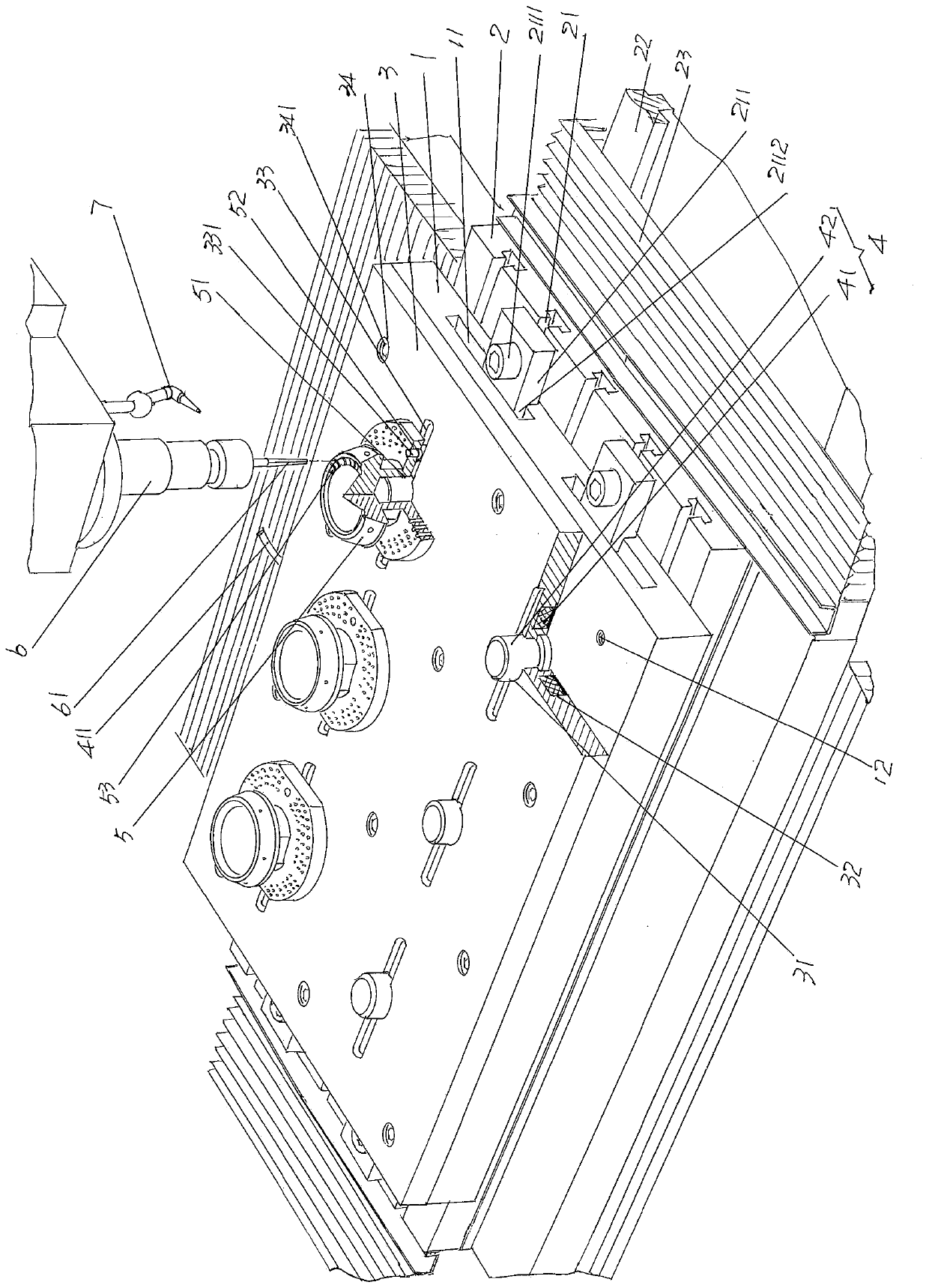
[0021] See figure 1 , shows a mold setting platform base plate 1, and this mold setting platform base plate 1 is fixed on the movable machine tool mobile working platform 2 of the machine tool under the use state; Shows a mold setting platform 3, and ...


PUM


Abstract

The invention belongs to the technical field of work fixtures and provides a clamp for machining of a glass mold bottle bottom mold. The clamp comprises a mold holding platform base plate fixed to a machine tool moving workbench, a mold holding platform fixed to the surface of the upward side of the mold holding platform base plate and a group of bottle bottom mold locating mechanisms arranged onthe mold holding platform. The clamp for machining of the glass mold bottle bottom mold is characterized in that each bottle bottom mold locating mechanism comprises an electromagnet and a mold holding locating column, wherein the electromagnet is arranged on the side, facing the mold holding platform base plate, of the mold holding platform and is electrically connected with an external electrical controller through a wire, the mold holding locating column is arranged on the mold holding platform and corresponds to the center position of the electromagnet, the bottom of the mold holding locating column is supported by the mold holding platform base plate, and the upper portion of the mold holding locating column extends out of the upper surface of the mold holding platform. The clamp formachining of the glass mold bottle bottom mold lowers manufacturing cost, lowers fault probability, guarantees machining progress, reduces the area of the occupied part of the mold holding platform, can increase the number of arranged bottle bottom molds at the same area, improves mold holding efficiency and guarantees the mold holding accuracy.

Description

technical field [0001] The invention belongs to the technical field of fixtures, and in particular relates to a fixture for processing glass mold bottle bottom molds. Background technique [0002] In the field of glass mold and its manufacturing technology, glass molds are usually divided into initial molds and forming molds. There are mouth molds and bottom molds matching the forming molds. The bottom molds are generally made of magnetizable mold steel. The processing items of the bottom mold, that is, the glass mold bottle bottom mold mentioned above, mainly include: rough machining outer circle (also called "rough turning outer circle"), finishing machining outer circle (also called "finish turning outer circle"), bottom drilling , reaming, engraving explosion-proof patterns on the upper surface of the mold bottom and drilling cooling holes for matching with the mold, etc. [0003] The machine tool used to engrave the explosion-proof pattern is usually a precision engrav...

Claims


Application Information

Patent Timeline
Patent Type & Authority Applications(China)
IPC IPC(8): B23Q3/06
CPCB23Q3/062
Inventor 苏秋君韩志强金旗王春坊王锦锋李旦
Owner CHANGSHU JIANHUA MOLD TECH
Learn More