Exhaust gas emission method of engine adopting push-back propeller

An exhaust method and technology for propellers, which are applied to the exhaust ports of power plants and other directions, can solve the problems of reduced propeller performance, increased resistance, increased windward area, etc., and achieve the effect of reducing the difficulty of use and maintenance

Inactive Publication Date: 2019-12-13
成会
View PDF3 Cites 0 Cited by
  • Summary
  • Abstract
  • Description
  • Claims
  • Application Information

AI Technical Summary

Problems solved by technology

[0004] First: Since the propeller of the push-back power design is located behind the engine, and the diameter of the blade is large, it is difficult for the waste gas discharged from the exhaust pipe to avoid the blade, and the waste gas discharged from the exhaust pipe pollutes the propeller and adheres to the blade surface, reducing propeller performance;
[0005] Second: Since the exhaust pipe extends downward or sideways for a certain distance, directly exposing the fuselage, the windward area increases and the resistance increases;
[...

Method used


Image

  • Exhaust gas emission method of engine adopting push-back propeller
  • Exhaust gas emission method of engine adopting push-back propeller
  • Exhaust gas emission method of engine adopting push-back propeller

Examples


Embodiment 1

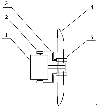
[0036] Such as figure 1 As shown, an air guide ring is set between the engine and the propeller, and the air guide ring and the propeller are fixed as one by connecting the fixed reed with the output shaft of the engine; the exhaust port of the engine exhaust pipe is connected with a guide Air pipe, the other end of the air guide pipe extends into the air guide ring pipe, and the air guide pipe does not make any contact with the inner and outer walls of the air guide ring pipe. When the propeller and the air guide ring pipe are rotating at high speed, the position of the air guide pipe is fixed and does not The propeller rotates together with the gas collar. The exhaust gas and waste residue discharged from the engine exhaust pipe are directly discharged to the rear end of the propeller after passing through the air guiding ring, that is, the side of the propeller not close to the engine, which completely solves the problem of traditional waste gas being sprayed directly on th...

Embodiment 2

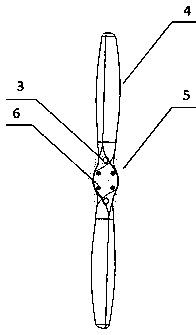
[0038] Such as Figure 4 As shown, the air guide ring includes two symmetrical parts, which are respectively arranged on both sides of the propeller. The shape of the end face connecting the air guide ring and the propeller must be consistent with the connecting surface of the screw. When connecting the connecting surface of the screw part, make sure that the air guide ring is completely attached to the propeller. The air guide ring tube divided into two must be two parts that are completely symmetrical. When the two parts are stuck in the middle of the propeller, the two parts of the air guide ring tube are fixed and locked with screws, and the guide tube can be realized. The air ring pipe and the propeller are fully locked and locked, so that the air guiding ring pipe and the propeller are integrated.

[0039] and figure 1 and Figure 4 The air guide pipe in the middle extends into the ring belt of the through air guide ring pipe. When the propeller rotates at high speed,...


PUM


Abstract

The invention discloses an exhaust gas emission method of an engine adopting a push-back propeller. Exhaust gas discharged from an engine exhaust gas emission pipe is discharged to the side, not closeto the engine, of the propeller through a gas guide device. The waste gas does not make contact with the propeller in the emission process. Different from a traditional engine exhaust gas direct emission manner, the exhaust gas emission method of the engine adopting the push-back propeller directly discharges the engine exhaust gas to the back side of the propeller through a gas guide ring pipe,so that the surfaces of blades of the propeller cannot be polluted. The exhaust gas emission pipe is not exposed outside the engine body in the manner that the gas guide pipe directly extends into thegas guide ring pipe at the root portion of the blades. The exhaust gas is directly discharged out from the back side of the propeller, so that the engine body, the blades and other components cannotbe polluted.

Description

technical field [0001] The invention relates to an aircraft power system, in particular to an engine exhaust method for a pushback propeller. Background technique [0002] Piston-type aeroengine is a reciprocating internal combustion engine that provides flight power for aircraft. The principle of the engine is to drive propellers such as air propellers to rotate to generate propulsion. Aviation piston engines are widely used in small and medium-sized unmanned aerial vehicles, trainer aircraft and other aviation vehicles due to their low fuel consumption, light weight and wide power range. [0003] Existing push-back piston-type aero-engines mostly use downward exhaust pipes, and the exhaust pipes are located in front of the propellers. In order to prevent the exhaust pipe waste gas from polluting the body, the exhaust pipes generally extend a certain distance. Although the exhaust design of this push-back propeller piston engine avoids pollution to the airframe itself, it ...

Claims


Application Information

Patent Timeline
IPC IPC(8): B64D33/04
CPCB64D33/04
Inventor 不公告发明人
Owner 成会
Why Eureka
Try Eureka