Polycrystalline silicon and iron alloy water-cooling heat-resistant cooling ingot mold

A ferroalloy and polysilicon technology, which is applied in the field of crystal ingot molds for casting, can solve problems such as slow heat exchange speed, adhesion, and unfixed size, and achieve the effects of fast heat exchange speed, reduced operating costs, and guaranteed service life

Inactive Publication Date: 2016-07-20
郭米慧
View PDF0 Cites 0 Cited by
  • Summary
  • Abstract
  • Description
  • Claims
  • Application Information

AI Technical Summary

Problems solved by technology

The body of the conventional ingot mold is a solid structure. During the cooling process of the liquid metal, a large amount of heat released by the cooling and solidification of the metal is absorbed by the body of the ingot mold. The temperature of the mold is relatively high, especially the parts that are in contact with the liquid metal are prone to sticking, slipping, and falling off. On the one hand, it seriously affects the service life of the ingot mold, and on the other hand, it also affects the quality of the solidified product and the smoothness of the casting surface. affected
In particular, polysilicon and ferroalloy products have a large surface area, but the size is not fixed, so the fixed bottom area of ​​the ingot mold will also affect the utilization rate of the equipment, thereby increasing the operating cost of the enterprise

Method used


Image

  • Polycrystalline silicon and iron alloy water-cooling heat-resistant cooling ingot mold

Examples


Embodiment 1

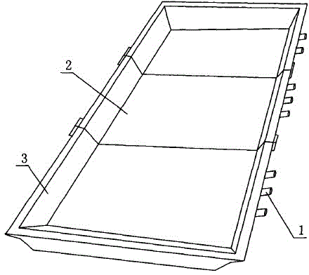
[0011] Such as figure 1 As shown, a water-cooled heat-resistant cooling ingot mold for polysilicon and ferroalloy includes a groove-shaped ingot mold body, and a water-cooling pipeline 1 is arranged at the bottom of the groove-shaped ingot mold body. Since the present invention arranges water-cooling pipes at the bottom of the groove-shaped ingot mold body, after a large amount of heat released by metal cooling and solidification is absorbed by the ingot mold body, it is not only transmitted to the air through heat radiation, but also through the large specific heat in the water-cooling pipes. The water quickly takes away the heat, and the heat exchange speed is extremely fast, so the temperature of the ingot mold drops quickly, and the parts in contact with the liquid metal can ensure the independence of its metallographic structure, and it is not easy to cause adhesion, slipping, and falling blocks. Phenomena such as ensuring the service life of the ingot mold, but also i...

Embodiment 2

[0013] Such as figure 1 As shown, a water-cooled heat-resistant cooling ingot mold for polycrystalline silicon and ferroalloy includes a groove-shaped ingot mold body. It is composed of 2 movable connections with the middle ingot module. The trough-shaped ingot mold body is composed of the end ingot module and the middle ingot module. The large body is turned into a combined block, which is very convenient to disassemble and reassemble ingots with different needs, which improves the utilization rate of the equipment, and further Reduced business operating costs.


PUM


Abstract

The invention discloses a polycrystalline silicon and iron alloy water-cooling heat-resistant cooling ingot mold. The polycrystalline silicon and iron alloy water-cooling heat-resistant cooling ingot mold comprises a slot-shaped ingot mold body, and a water-cooling pipeline is arranged at the bottom of the slot-shaped mold body. As the water-cooling pipeline is arranged at the bottom of the slot-shaped mold body, after being absorbed by the ingot mold body, a large amount of heat released by cooled solidification of metal is transmitted to air through thermal irradiation and carried away quickly by high-specific-heat water in the water-cooling pipeline, the ingot mold is cooled fast as the heat exchange speed is extremely high, the independence of the gold phase structure of the portion, making contact with molten metal, of the ingot mold can be ensured, and the phenomena of adhesion, scratches, chip off-falling and the like are not likely to occur; the service life of the ingot mold is ensured; the quality of solidified products is also improved; and the surface smoothness of castings is not affected.

Description

technical field [0001] The invention relates to a crystal ingot mold for casting, in particular to a water-cooled heat-resistant cooling ingot mold for polycrystalline silicon and iron alloy. Background technique [0002] The cooling ingot mold is a kind of equipment commonly used in the foundry industry, which is used for the crystallization and solidification of liquid metal. The body of the conventional ingot mold is a solid structure. During the cooling process of the liquid metal, a large amount of heat released by the cooling and solidification of the metal is absorbed by the body of the ingot mold. The temperature of the mold is relatively high, especially the parts that are in contact with the liquid metal are prone to sticking, slipping, and falling off. On the one hand, it seriously affects the service life of the ingot mold, and on the other hand, it also affects the quality of the solidified product and the smoothness of the casting surface. affected. In partic...

Claims


Application Information

Patent Timeline
Patent Type & Authority Applications(China)
IPC IPC(8): B22D7/06B22D7/08C30B29/06C30B28/06
Inventor 郭米慧
Owner 郭米慧
Why Eureka
Try Eureka