Battery pack cooling structure, battery shell and battery system

A cooling structure and battery pack technology, applied in the field of electric vehicles, can solve the problems of battery system maintenance and management difficulties, the inability to discharge heat from the battery pack in time, and the inability of the battery pack to run stably, so as to facilitate orderly management and improve safety. performance and stability, the effect of reducing the occupied space

Pending Publication Date: 2019-12-13
GAC AION NEW ENERGY AUTOMOBILE CO LTD
View PDF0 Cites 3 Cited by
  • Summary
  • Abstract
  • Description
  • Claims
  • Application Information

AI Technical Summary

Problems solved by technology

Since the cooling water pipe is separated from the battery pack, during the cooling process, the cooling water pipe and the battery pack are separated from each other to cool down. Therefore, it is easy to cause the heat of the battery pack to be discharged in time, and the cooling efficiency is low, resulting in the unstable operation of the battery pack.
At the same time, the traditional cooling water pipes are laid in the battery case, which reduces the space in the battery case and the arrangement of equipment is chaotic, which makes the maintenance and management of the battery system extremely difficult.

Method used


Image

  • Battery pack cooling structure, battery shell and battery system
  • Battery pack cooling structure, battery shell and battery system
  • Battery pack cooling structure, battery shell and battery system

Examples


Embodiment Construction

[0043] In order to make the object, technical solution and advantages of the present invention clearer, the present invention will be further described in detail below in conjunction with the accompanying drawings and specific implementation methods. It should be understood that the specific embodiments described here are only used to explain the present invention, and do not limit the protection scope of the present invention.

[0044] It should be noted that when an element is referred to as being “fixed” to another element, it can be directly on the other element or there can also be an intervening element. When an element is referred to as being "connected to" another element, it can be directly connected to the other element or intervening elements may also be present. The terms "vertical," "horizontal," "left," "right," and similar expressions are used herein for purposes of illustration only and are not intended to represent the only embodiments.

[0045] Unless otherw...


PUM


Abstract

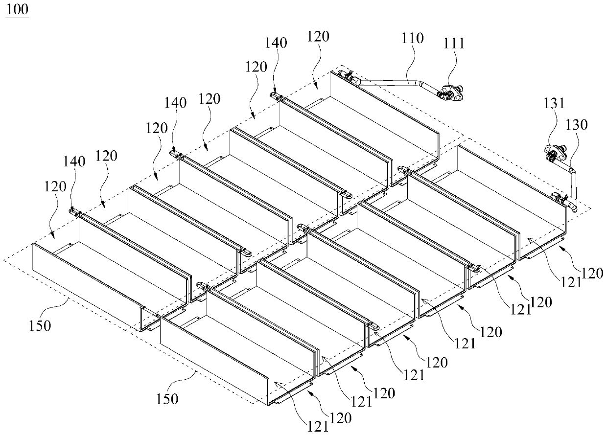
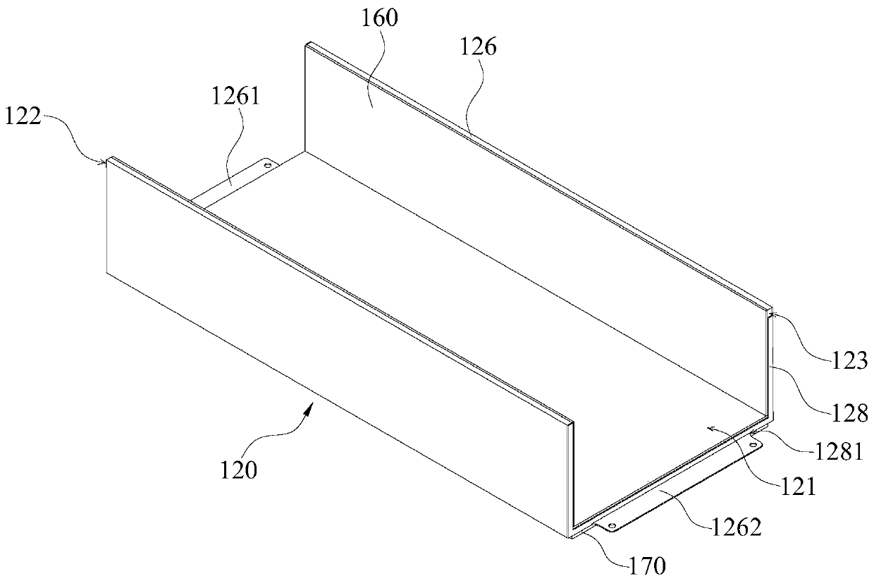
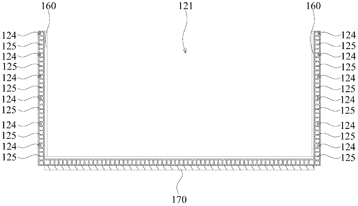
The invention discloses a battery pack cooling structure, a battery shell and a battery system. Cooling water is introduced into cooling channels through a water incoming pipe; the cooling water subjected to heat exchange is outputted through a water outgoing pipe; and therefore, the cooling water continuously and stably flows in cooling bodies, and battery packs can be stably and continuously cooled. Due to the fact that the cooling bodies are provided with installation grooves used for containing the battery packs, when the battery packs are installed in the installation grooves, a heat exchange mode between the battery packs and the cooling bodies is a direct contact heat exchange mode; heat on the battery packs is directly absorbed through the cooling water in the cooling channels; theheat on the battery packs is discharged in time; the cooling efficiency of the battery packs is improved; a large amount of heat is prevented from being gathered in the battery packs; effective and stable cooling is achieved; the battery packs are always in good working states; and the safe and stable operation of the battery packs is guaranteed; and space in the shell, which is occupied by the battery pack cooling structure, is reduced, so that the inner structure of the shell is more reasonable and compact.

Description

technical field [0001] The invention relates to the technical field of electric vehicles, in particular to a battery pack cooling structure, a battery shell and a battery system. Background technique [0002] For electric vehicles, the battery pack technology is very important. The stability and safety of the battery pack directly determine the performance of the electric vehicle. The stability and safe operation of the battery pack mainly depend on issues such as waterproof, anti-collision and cooling. In terms of cooling, traditional battery packs generally use cooling water pipes to cool down. The cooling water pipes are laid in the battery case, and the battery case is cooled through the cooling water pipes. Since the cooling water pipe is separated from the battery pack, during the cooling process, the cooling water pipe and the battery pack are separated from each other to cool down. Therefore, it is easy to cause the heat of the battery pack to not be discharged in ti...

Claims


Application Information

Patent Timeline
Patent Type & Authority Applications(China)
IPC IPC(8): H01M10/613H01M10/625H01M10/6556H01M10/6567H01M2/10
CPCH01M10/613H01M10/625H01M10/6556H01M10/6567H01M50/20Y02E60/10
Inventor 周青华许俊海廖光明周超何凯欣刘太刚
Owner GAC AION NEW ENERGY AUTOMOBILE CO LTD
Why Eureka
Try Eureka