Annular channel structure between stator and rotor of shielded motor

An annular flow channel, shielded motor technology, applied in the direction of magnetic circuit shape/style/structure, electric components, electromechanical devices, etc., can solve the difficulty of further improving the speed and power density of shielded motors, increase cooling measures and structural weight, and reduce shielding. The reliability of motor operation and other issues can be reduced to reduce fluid friction loss, improve cooling performance, and improve cooling and heat transfer performance.

Active Publication Date: 2021-03-16
SHANGHAI INST OF SPACE PROPULSION
View PDF8 Cites 0 Cited by
  • Summary
  • Abstract
  • Description
  • Claims
  • Application Information

AI Technical Summary

Problems solved by technology

[0004] However, because the rotor structure (rotating shaft, bearing, etc.) The loss makes the efficiency of the shielded motor drop significantly, and the temperature of the motor rises sharply
This will not only add more cooling measures and structural weight, increase the complexity and cost of maintenance, but also reduce the working reliability of the shielded motor, and it is difficult to further improve the speed and power density of the shielded motor

Method used


Image

  • Annular channel structure between stator and rotor of shielded motor
  • Annular channel structure between stator and rotor of shielded motor
  • Annular channel structure between stator and rotor of shielded motor

Examples


Embodiment 1

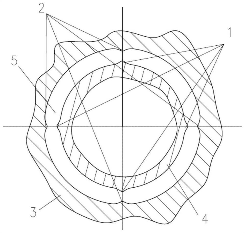
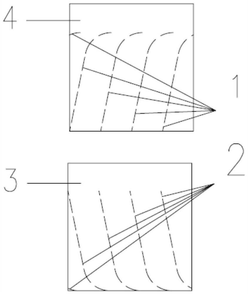
[0051] Figure 1 ~ Figure 2 It is a schematic diagram of the cross-section and the unfolded structure of the annular flow passage structure between the stator and the rotor of the shielded motor provided in Embodiment 1 of the present invention. Such as Figure 1 ~ Figure 2 As shown, the annular flow channel structure between the stator and rotor of the shielded motor provided by the present invention includes: a stator shielding sleeve (generally made of metal material) 3 with discontinuous flow guide ribs 2 on the inner cylindrical surface, and a discontinuous flow guide rib on the outer cylindrical surface. The rotor shielding sleeve (usually metal material) 4 of the rib 1, and the annular flow channel 5 between the stator shielding sleeve and the rotor shielding sleeve.

[0052] figure 1 The medium fluid flows from top to bottom perpendicular to the paper surface, and the rotor rotates clockwise; figure 2 The medium fluid flows from top to bottom along the paper, and t...

Embodiment 2

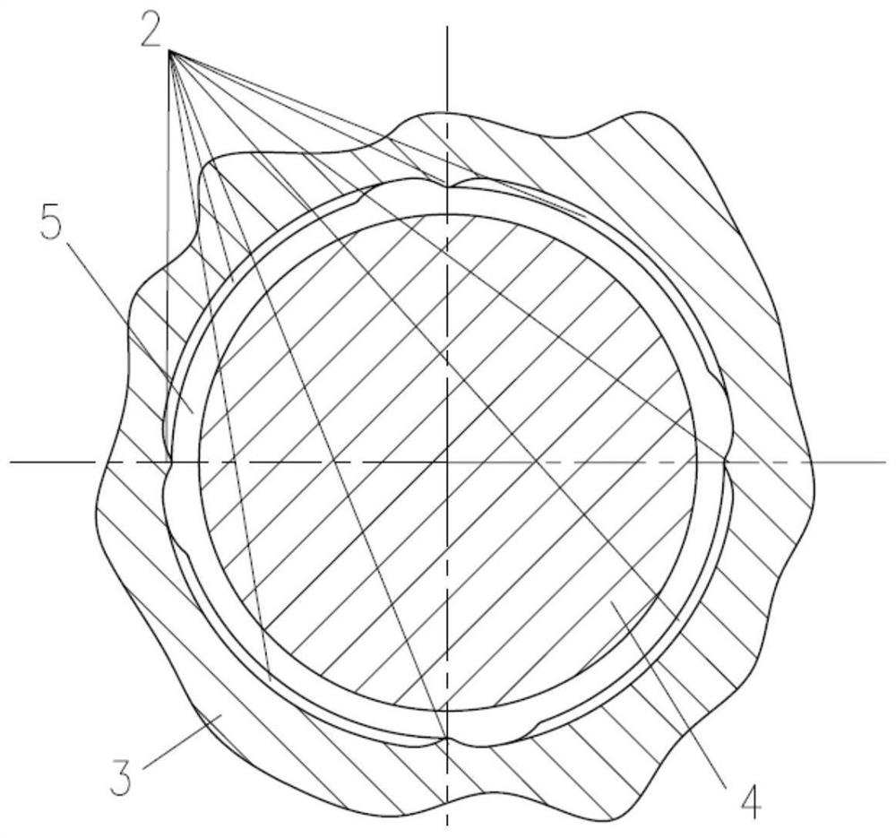
[0054] Figure 3 ~ Figure 4 It is a schematic diagram of the cross-section and the unfolded structure of the annular flow passage structure between the stator and the rotor of the shielded motor provided by Embodiment 2 of the present invention. Such as Figure 3 ~ Figure 4 As shown, the annular flow channel structure between the stator and rotor of the shielded motor provided by the present invention includes: a stator shielding sleeve 3 with a continuous guide rib 2 on the inner cylindrical surface, a rotor shielding sleeve 4 without a guide rib on the outer cylindrical surface, and a stator The annular flow channel 5 between the shielding sleeve and the rotor shielding sleeve.

[0055] image 3 The medium fluid flows from top to bottom perpendicular to the paper surface, and the rotor rotates clockwise; Figure 4 The medium fluid flows from top to bottom along the paper, and the rotor rotates from left to right along the paper.

[0056] In other embodiments of the prese...


PUM


Abstract

The invention discloses an annular flow channel structure between a shielded motor stator and a rotor. The structure comprises a stator shielding sleeve, a rotor shielding sleeve and an annular flow channel between the stator shielding sleeve and the rotor shielding sleeve. An inner cylindrical surface of the stator shielding sleeve and / or an outer cylindrical surface of the rotor shielding sleeve are / is provided with flow guide convex ribs, and a section shape, a size, a number, layout and the like of the flow guide convex ribs can be set according to specific technical requirements and application environments. By using the annular flow channel structure between the shielded motor stator and the rotor, on one hand, working efficiency, a rotating speed and power density of the shielded motor are improved; and on the other hand, a fault probability caused by motor overheating, cooling medium vaporization and the like can be reduced.

Description

technical field [0001] The invention relates to the technical field of shielded motors, in particular to an annular channel structure between the stator and rotor of the shielded motor. Background technique [0002] In the fields of petrochemical, nuclear power, aerospace and refrigeration, especially when conveying high temperature, high pressure, flammable, explosive, corrosive or highly toxic fluid media, the structure of dynamic seal (and the risk of leakage caused by it) has been cancelled. The fully enclosed canned pump has unique due advantages. [0003] For example, the patent document CN110043472A discloses a canned motor for pumps that can transport liquids containing particles. The canned motor for pumps includes a motor chamber, a pump chamber and a negative pressure suction device. The output end of the motor chamber is connected to the pump chamber. The negative pressure suction device includes a first negative pressure suction device and a second negative pre...

Claims


Application Information

Patent Timeline
Patent Type & Authority Patents(China)
IPC IPC(8): H02K1/20H02K1/32H02K9/197
CPCH02K1/20H02K1/32H02K9/197H02K2201/03H02K2213/03
Inventor 程诚李小芳王浩明田桂张志远林庆国
Owner SHANGHAI INST OF SPACE PROPULSION
Why Eureka
Try Eureka