Supercharge Your Innovation With Domain-Expert AI Agents!

Optical module and electronic equipment

A technology of optical modules and filter layers, which is applied in televisions, electrical components, color TVs, etc., can solve problems such as low assembly efficiency, complicated filter process, unfavorable miniaturization design of optical modules, and improve assembly efficiency , The effect of simplifying the assembly process

Inactive Publication Date: 2019-12-13
VIVO MOBILE COMM CO LTD
View PDF7 Cites 1 Cited by
  • Summary
  • Abstract
  • Description
  • Claims
  • Application Information

AI Technical Summary

Problems solved by technology

[0005] The invention discloses an optical module and electronic equipment to solve the problems of complex process, low assembly efficiency and unfavorable miniaturization design of the optical module in the assembling method of the optical filter in the optical module of the current electronic equipment

Method used


Image

  • Optical module and electronic equipment
  • Optical module and electronic equipment
  • Optical module and electronic equipment

Examples


Embodiment Construction

[0033] In order to make the purpose, technical solution and advantages of the present invention clearer, the technical solution of the present invention will be clearly and completely described below in conjunction with specific embodiments of the present invention and corresponding drawings. Apparently, the described embodiments are only some of the embodiments of the present invention, but not all of them. Based on the embodiments of the present invention, all other embodiments obtained by persons of ordinary skill in the art without making creative efforts belong to the protection scope of the present invention.

[0034] The technical solutions disclosed by various embodiments of the present invention will be described in detail below in conjunction with the accompanying drawings.

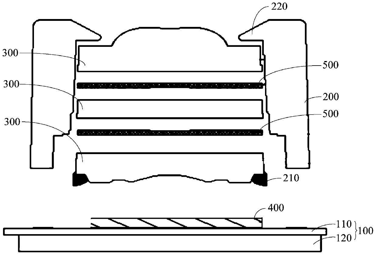
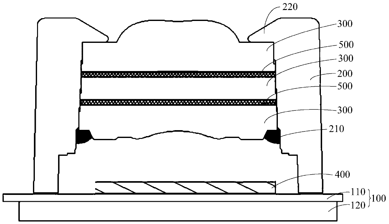
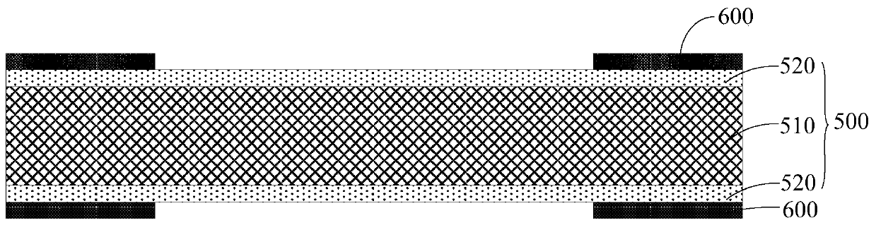
[0035] Please refer to Figure 1-Figure 4 , the embodiment of the present invention discloses an optical module, and the disclosed optical module can be applied to electronic equipment. The di...


PUM


Abstract

The invention discloses an optical module. The optical module discloses a substrate (100), a lens bracket (200), at least two lenses (300), a photosensitive chip (400) and at least one optical filter(500); the lens bracket (200) is arranged on the base plate (100); the photosensitive chip (400) is arranged on the substrate (100) and located in an area defined by the lens support (200); the at least two lenses (300) are installed on the lens support (200) and are arranged opposite to the photosensitive chip (400), and the optical filter (500) is clamped between the two adjacent lenses (300) and is arranged opposite to the photosensitive chip (400). According to the scheme, the problems that the process is complex, the assembly efficiency is low and the miniaturization design of the opticalmodule is not facilitated in the assembly mode of the optical filter in the optical module of the existing electronic equipment can be solved. The invention discloses an electronic device.

Description

technical field [0001] The invention relates to the technical field of communication equipment, in particular to an optical module and electronic equipment. Background technique [0002] With the improvement of user needs, electronic devices have more and more functions. At the same time, electronic devices are equipped with more and more optical modules, such as camera modules and optical fingerprint recognition modules. The optical performance of the optical module will directly affect the overall performance of the electronic device. [0003] In current electronic equipment, the optical module is usually equipped with an optical filter, which can filter out the light that causes adverse interference caused by the optical module. For example, the optical filter is usually an infrared filter, and the infrared filter can The infrared light in the ambient light is filtered out, so as to avoid the influence of the infrared light during the imaging process of the optical modul...

Claims


Application Information

Patent Timeline
IPC IPC(8): H04N5/225
CPCH04N23/54H04N23/55
Inventor 张涛
Owner VIVO MOBILE COMM CO LTD
Features
  • R&D
  • Intellectual Property
  • Life Sciences
  • Materials
  • Tech Scout
  • Unparalleled Data Quality
  • Higher Quality Content
  • 60% Fewer Hallucinations
Learn More