Thyroid ultrasound detection device and detection method thereof

An ultrasonic detection and thyroid technology, which is applied in the structure of ultrasonic/sonic/infrasonic diagnostic equipment, organ movement/change detection, ultrasonic/sonic/infrasonic diagnosis, etc. Process, poor consistency and other problems, to achieve the effect of convenient and fast scanning, reduce professional human resource costs, and accurate diagnosis

Active Publication Date: 2019-12-17
SHANTOU INST OF UITRASONIC INSTR CO LTD
View PDF11 Cites 8 Cited by
  • Summary
  • Abstract
  • Description
  • Claims
  • Application Information

AI Technical Summary

Problems solved by technology

Since the detected part is scanned with a hand-held probe, the consistency of the direction and interval of each section detected during the scanning process is very poor, and it is impossible to assemble a three-dimensional imag...

Method used


Image

  • Thyroid ultrasound detection device and detection method thereof
  • Thyroid ultrasound detection device and detection method thereof
  • Thyroid ultrasound detection device and detection method thereof

Examples


Embodiment 1

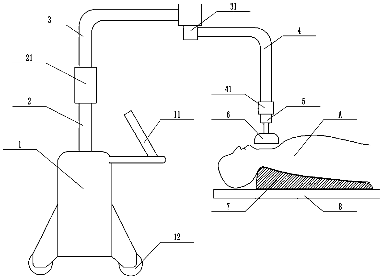
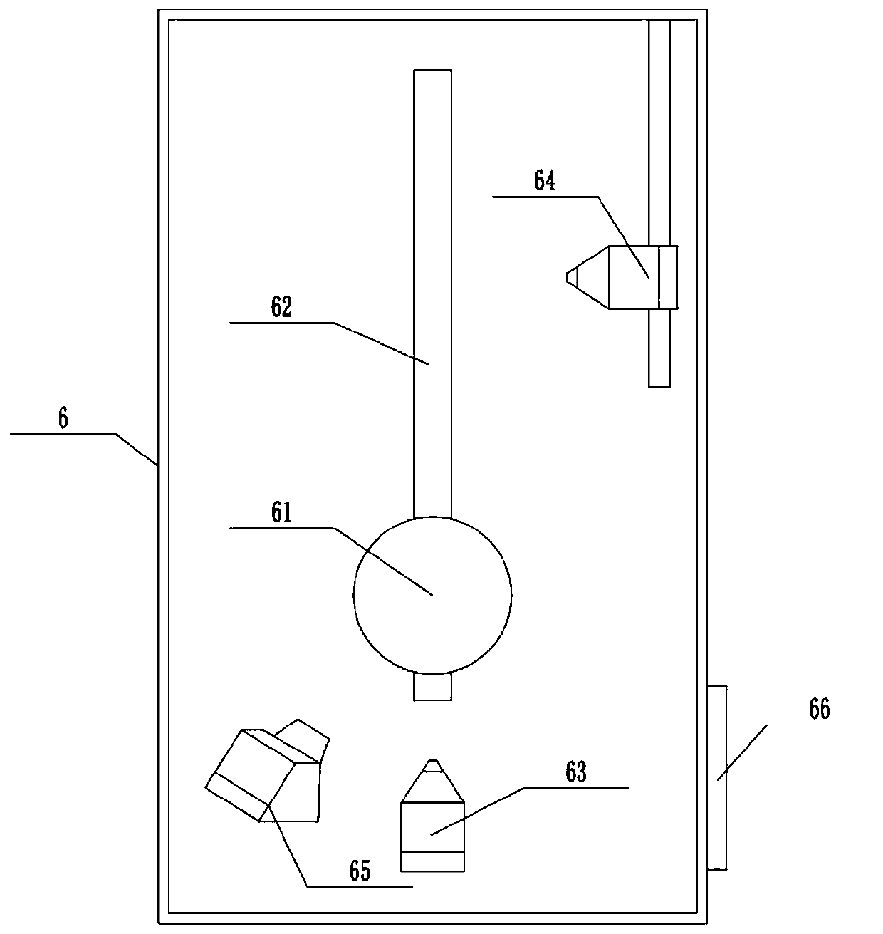
[0038] A kind of thyroid ultrasonic detection equipment of embodiment 1 of the present invention such as Figure 1-3 As shown, it includes an ultrasonic host 1 and a testing bed 8, the ultrasonic host 1 is placed adjacent to the testing bed 8, and also includes a supporting mobile device, a scanning device 6 and an auxiliary device 7, and the supporting mobile device is fixedly installed On the ultrasonic host machine 1, the scanning device 6 is arranged at the end of the supporting mobile device and suspended on the testing bed 8, the auxiliary device 7 is placed on the testing bed 8, the The auxiliary device 7 conforms to the design of human body mechanics, and the supporting mobile device and the scanning device 6 are respectively electrically connected with the ultrasonic host 1 . The auxiliary device 7 is used to adjust the neck of the person A to be detected, and perform non-interfering scanning operations on the neck, so that the detected part is at an angle that is con...

Embodiment 2

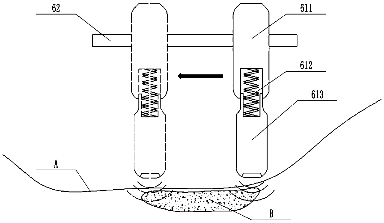
[0046] This embodiment is basically the same as Embodiment 1, the difference is: as Figure 4 As shown, the moving rod 62' is arc-shaped, because the neck of a person is approximately circular, and if longitudinal sweeping is used, the moving rod 62' only needs to be straight to ensure that the ultrasonic probe 61 basically scans on one plane. However, when the horizontal scan is adopted, the plane of the scan will be an arc surface. Therefore, it is necessary to adapt the moving rod 62' to the physiological structure of the human neck, so that the scan path of the ultrasonic probe 61 becomes arc-shaped. , therefore, it is necessary to use an arc-shaped moving rod 62' to ensure the smooth progress of the scanning. The scanning methods of Embodiment 1 and Embodiment 2 are basically the same, and are only changed due to the specific conditions of the detected parts. Other such changes should also be considered to fall within the protection scope of the present invention.


PUM


Abstract

The invention discloses a thyroid ultrasound detection device and a detection method thereof. The detection device comprises a main ultrasound machine and a detection bed. The main ultrasound machineis placed adjacent to the detection bed, and detection device further includes a supporting moving device, a scanning device and an auxiliary device; and the supporting moving device is fixedly installed on the main ultrasound machine, the scanning device is disposed on the end part of the supporting moving device and is suspended from the detection bed, the auxiliary device is placed on the detection bed, the auxiliary device conforms to the human body mechanical design, and the supporting moving device and the scanning device are electrically connected with the main ultrasound machine separately. According to the thyroid ultrasound detection device and the detection method thereof, the cost of professional human resources is reduced, scanning is easier and faster, the waiting time of a subject is shortened, meanwhile, the quality of image information obtained by the scanning is higher, the diagnosis is more accurate, and an ultrasonic detection result is more standard and more versatile.

Description

technical field [0001] The invention belongs to the technical field of ultrasonic detection equipment, and in particular relates to a thyroid ultrasonic detection equipment and a detection method thereof. Background technique [0002] Ultrasound diagnosis of the thyroid gland is generally performed by a doctor holding an ultrasound probe to scan back and forth at the detected site, and the doctor watches the ultrasound images while scanning for diagnosis. This process has high requirements on the doctor's scanning technique, and requires a doctor with strong professional skills to operate, and the diagnosis can only be made at the same time as the scan, and the information of the ultrasound test will not be recorded and stored. [0003] The current ultrasonic detection system is mainly composed of an ultrasonic probe and an ultrasonic host. The ultrasonic probe converts the acoustic signal into an electrical signal and sends it to the ultrasonic host for calculation and proc...

Claims


Application Information

Patent Timeline
IPC IPC(8): A61B8/08A61B8/00
CPCA61B8/085A61B8/44A61B8/40A61B8/42
Inventor 李德来苏树钿蔡泽杭陈英怀
Owner SHANTOU INST OF UITRASONIC INSTR CO LTD
Why Eureka
Try Eureka