
A weighing mixer

A mixer and weighing technology, which is applied to mixers, mixers with rotating stirring devices, mixer accessories, etc., can solve problems such as large labor loss, waste, and irregular measuring methods, so as to solve waste and speed up the speed Effect

Active Publication Date: 2022-03-15
东莞市同锐机械有限公司
View PDF5 Cites 0 Cited by
  • Summary
  • Abstract
  • Description
  • Claims
  • Application Information

AI Technical Summary

Problems solved by technology

[0008] In order to solve the above problems, the present invention provides a weighing mixing material mixer, which aims to solve the problems of unsatisfactory mixing effect, waste phenomenon in the feeding process, large labor loss and irregular measuring methods in the background technology

Method used


Image

  • A weighing mixer
  • A weighing mixer
  • A weighing mixer

Examples


Embodiment Construction

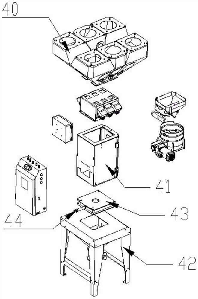
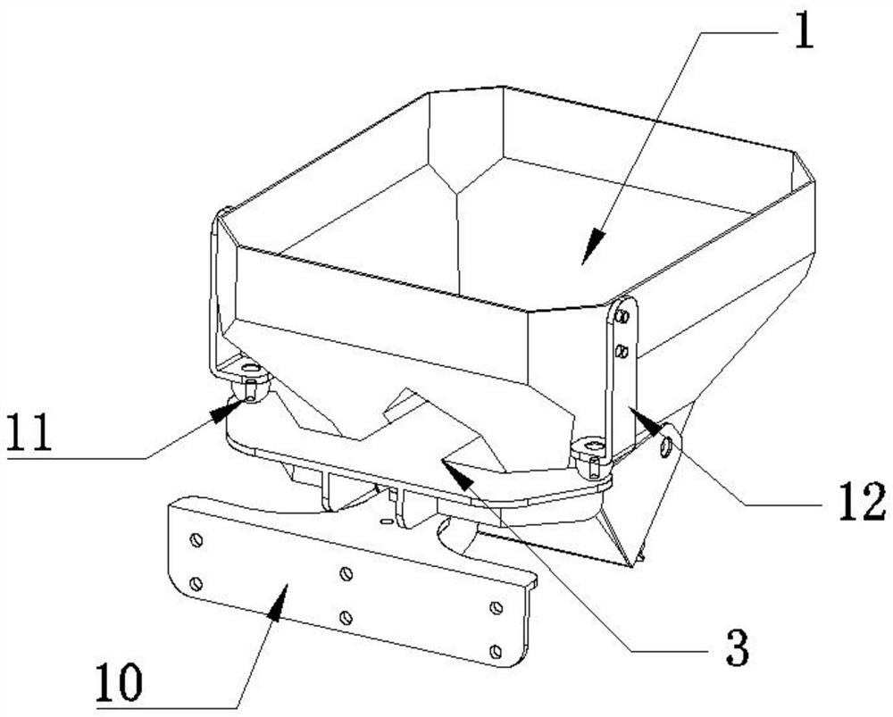
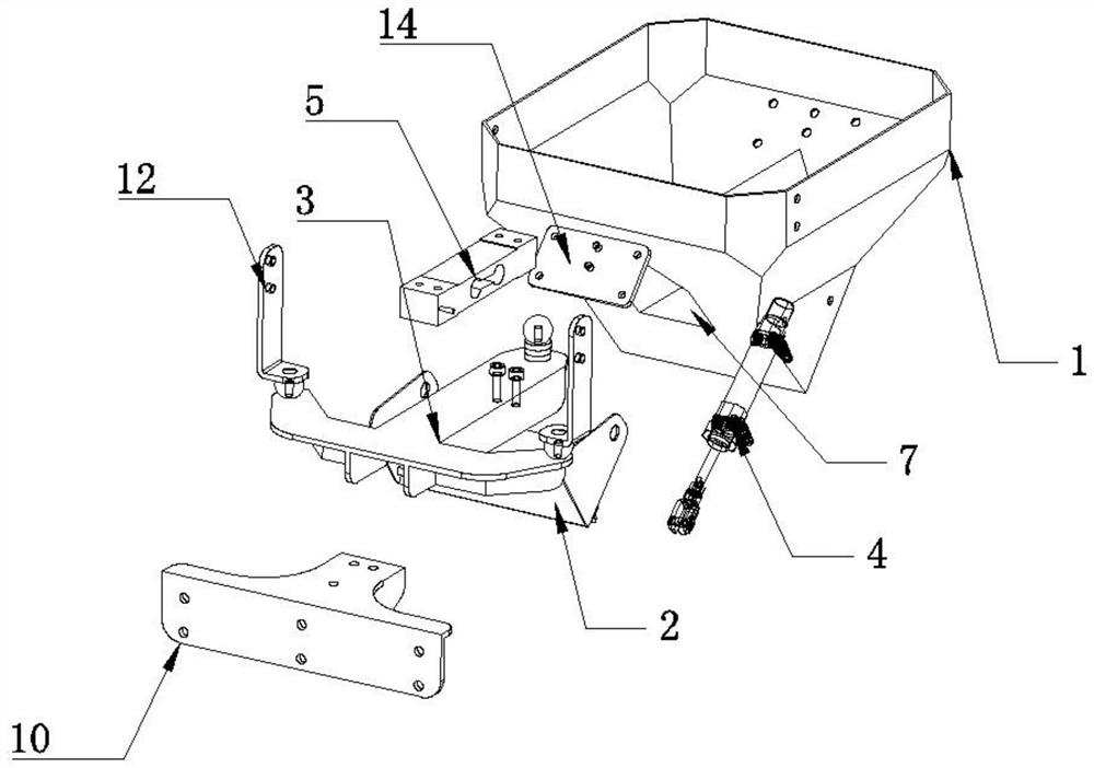
[0046] see Figure 1-15 As shown, the present invention relates to a weighing mixer, including: a weighing device, the weighing device includes a weighing pan 1, a weighing pan material closing plate 2, a weighing pan support frame 3, and a first telescopic cylinder 4 , the first load cell 5, the spacer belt, the surface of the weighing pan 1 is connected to the internal feeding port, and the spacer belt runs through the opposite sides of the weighing pan 1 to divide the weighing pan 1 into two feeding chambers 6, and Both ends of the spacer are openings, and the openings penetrate the inside of the spacer to form a channel 7 for the weighing pan support frame 3 to pass through. There is a weighing pan discharge port 8 corresponding to the blanking cavity 6, the first telescopic cylinder 4 is arranged on the side of the weighing pan 1, and the weighing pan material closing plate 2 cover is arranged on the surface of the weighing pan discharge port 8 and is connected with the f...


PUM


Abstract

The invention relates to the field of mixing equipment, especially a weighing and mixing machine. The material enters the weighing pan from the discharge port, and the material in the weighing pan enters the feeding cavity through the interval belt. The interval belt has The passage for the weighing pan supporting frame to pass through, and the first load cell is arranged at the lower end of the weighing pan supporting frame, and the material enters into the feeding cavity, and the pressure signal is converted into an electrical signal by the first load cell, thereby obtaining Weighing data, the first stirring blade is circular, the second stirring blade is arc-shaped, and the oblique setting of the first stirring blade and the second stirring blade can make the stirring liquid form a spiral shape. Stir.

Description

technical field [0001] The invention relates to the field of mixing equipment, in particular to a weighing mixer. Background technique [0002] After searching by the applicant, it is found that any processing and application of particles will use the mixer, especially in the production line, as the mixing object of the material. The materials are fed, weighed and then put into the mixing process, which is convenient to achieve particle mixing to obtain a uniform mixture of particles. [0003] Since the existing mixers are designed with dual pressure sensors, in the actual use process, the required center of gravity range (generally within 150mm) of the single cantilever beam pressure sensor is small and the data acquisition will be inaccurate, so it is designed as a dual pressure sensor. solve. [0004] However, because the signal linearity of the dual pressure sensor after delivery is not consistent with the signal linearity before leaving the factory, in actual use, the...

Claims


Application Information

Patent Timeline
Patent Type & Authority Patents(China)
IPC IPC(8): B01F27/90B01F35/71B01F35/21G01G19/32
CPCG01G19/32B01F27/90B01F35/43B01F35/714B01F35/71
Inventor 叶乃阔张君松
Owner 东莞市同锐机械有限公司
Learn More