Device for drying glass powder by utilizing waste heat

A glass powder, waste heat technology, applied in heating devices, drying, dryers and other directions, can solve the problems of energy consumption, reduce energy consumption and production costs, and achieve the effect of reducing production costs and energy consumption

CN111102825AInactive Publication Date: 2020-05-05湖北如日电气股份有限公司
0 Cites 0 Cited by

Patent Information

Authority / Receiving Office
CN · China
Patent Type
Applications(China)
Current Assignee / Owner
Publication Date
2020-05-05
Estimated Expiration
Not applicable · inactive patent

Smart Images

  • Figure 1
    Figure 1
  • Figure 2
    Figure 2
Patent Text Reader

Abstract

The invention provides a device for drying glass powder by utilizing waste heat. The device is characterized in that heat absorption boxes are arranged on high-temperature zones on the two sides of amelting furnace for melting the glass powder correspondingly, and the heat absorption boxes on the two sides communicate through a communicating pipe; the heat absorption box on one side communicateswith an air blower through an air supply pipe, and the heat absorption box is provided with a hot air pipe to communicate with a drying chamber above a rack of the LED material drying device; a tail gas heat exchange chamber is arranged at the tail gas exhaust end of the melting furnace, a steam-water diverging pipe is arranged above the tail gas heat exchange chamber, and the steam-water diverging pipe is provided with a water supply pipe and a steam exhaust pipe, wherein the outer end of the steam exhaust pipe is led into steam interlayers on the inner periphery and the outer periphery of the drying chamber; and an induced draft fan is arranged at the communication position between the hot air pipe and the drying chamber. According to the device, through the scientific design, the wasteheat at the outer side and the tail of the melting furnace for melting LED glass is fully utilized; and the waste heat is used for drying the LED glass powder, so that the resource waste is reduced, and the production cost is reduced.
Need to check novelty before this filing date? Find Prior Art

Description

Technical field

[0001] The invention relates to a glass powder drying device, in particular to a device that uses waste heat to dry glass powder. Background technique

[0002] In the production of glass products, the glass powder is dehydrated and dried. The traditional method is to dehydrate the glass powder and put it into a cylindrical dryer to heat it with fuel at the periphery and bottom for drying. The traditional drying method has the problems of using energy and poor operating environment, and at the same time directly increases the manufacturing cost. Summary of the invention

[0003] The purpose of the present invention is to solve the above-mentioned problem of energy consumption and provide a device for drying glass frit by using waste heat, so that the waste heat can be fully utilized, which is beneficial to reduce energy consumption and production costs.

[0004] The present invention includes a melting furnace, and the adopted technical scheme is: heat absorption box...

Examples

Embodiment Construction

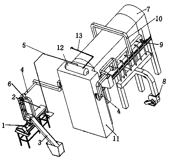
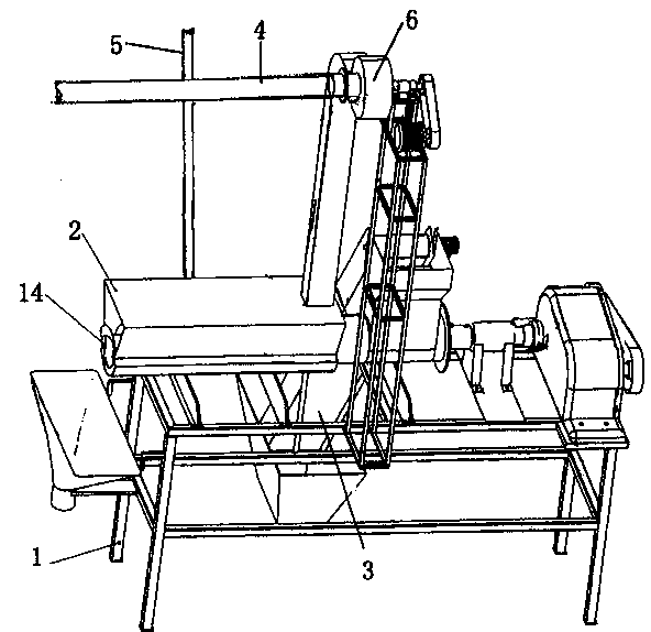
[0012] figure 1 Shown: the high temperature zone on both sides of the melting furnace 7 for melting glass frit is provided with heat absorption boxes 9 respectively, and the heat absorption boxes 9 on both sides are connected through a connecting pipe 10; one side of the heat absorption box 9 is connected to a blower 8 through a blowing pipe , The heat absorption box 9 is provided with a hot air pipe 4 connected to the drying chamber 2 above the LED material drying equipment rack 1; a tail gas heat exchange chamber 11 is provided at the tail gas discharge end of the melting furnace 7, and the tail gas heat exchange A steam-water flow pipe 12 is provided above the chamber 11. The steam-water flow pipe 12 is equipped with a water supply pipe 13 and a steam discharge pipe 5. The outer end of the steam discharge pipe 5 leads into the steam interlayer on the inner and outer circumferences of the drying chamber 2. An induced draft fan 6 is installed in the connection with the drying c...