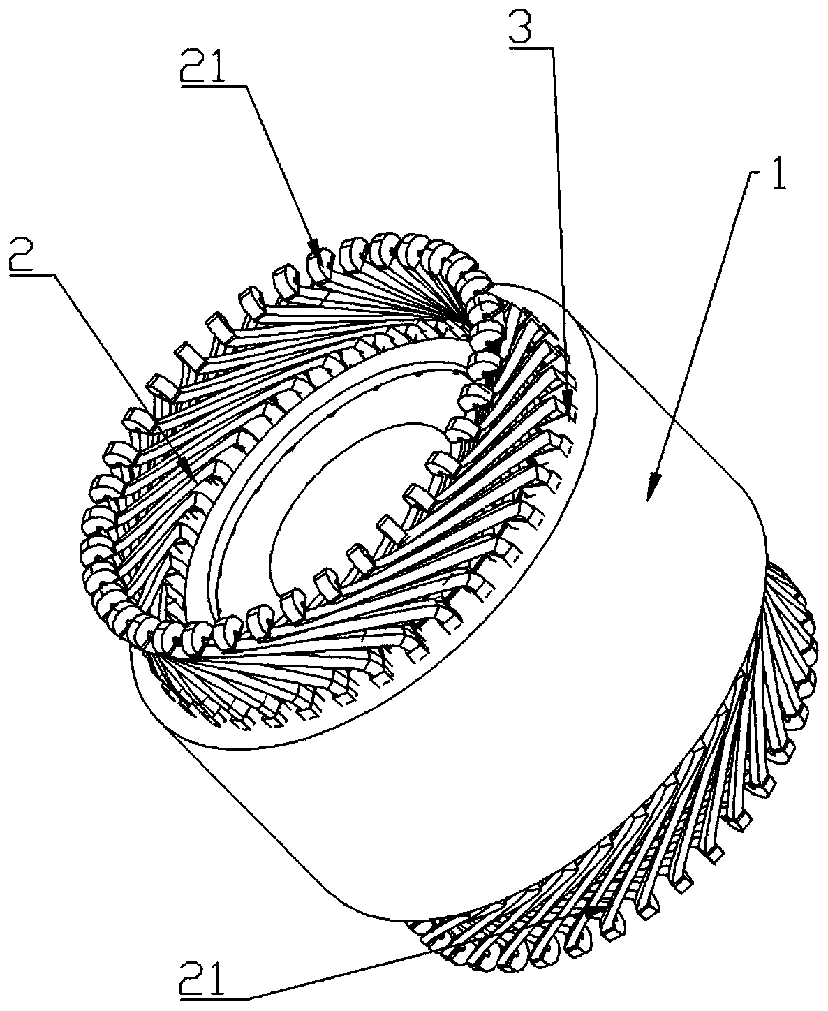
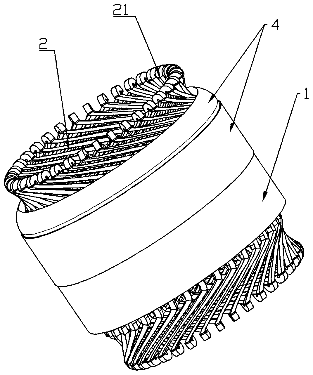
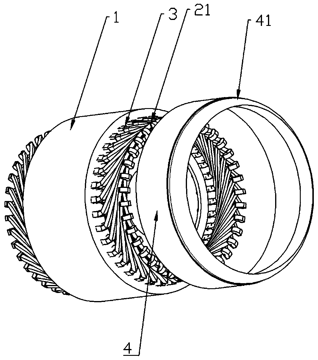
Heat radiation structure of motor stator winding

A technology of motor stator and heat dissipation structure, which is applied to windings, electric components, electrical components, etc., and can solve problems such as low efficiency and complex heat dissipation structure of the motor

Pending Publication Date: 2019-12-17
深圳山谷风科技有限公司
View PDF0 Cites 5 Cited by
  • Summary
  • Abstract
  • Description
  • Claims
  • Application Information

AI Technical Summary

Problems solved by technology

[0004] Aiming at the deficiencies in the above-mentioned technologies, the present invention provides a method to solve the problem that the heat dissipation structure of the existing motor proposed in the above-mentioned background technology is too complicated and the efficiency is not high.

Method used


Image

  • Heat radiation structure of motor stator winding
  • Heat radiation structure of motor stator winding
  • Heat radiation structure of motor stator winding

Examples


Embodiment 1

[0033] The Maer wind motor is used as the test motor stator winding, and the centralized winding method is adopted, and the motor insulation level is B; the test is carried out by the resistance temperature measurement method, and the ambient temperature is 28°C during the test; and two motors are prepared as this test. The samples of the second experiment are numbered as motor No. 1 and motor No. 2; among them:

[0034] Motor No. 1: It is an unprocessed blank motor, and there is no other additional heat dissipation structure;

[0035] Motor No. 2: a processing motor with a heat-conducting structural layer arranged between the end of the winding and the stator core;

[0036] The thermally conductive structure layer uses thermally conductive silicone grease, and the test is carried out after the thermally conductive silicone grease is completely cured.

[0037] On No. 1 motor and No. 2 motor, there are 9 temperature measuring points, numbered A, B, C, D, E, F, G, H, I. On the...

Embodiment 2

[0042] Wenzhou Weipu Motor is used as the test motor stator winding, and the distributed winding method is adopted, and the insulation level of the motor is Class E; the test is carried out by directly applying voltage to the stator winding, and two motors are prepared as samples for this experiment. And numbered as No. 1 motor and No. 2 motor; the test time is 120min, of which:

[0043] Motor No. 1: It is an unprocessed blank motor, and there is no other additional heat dissipation structure;

[0044] Motor No. 2: a processing motor with a heat-conducting structural layer arranged between the end of the winding and the stator core;

[0045] On the No. 1 motor and the No. 2 motor, there are 4 temperature measuring points, numbered A, B, C, and D. On the No. 1 motor, A and B are set at the winding end of one side and the temperature measuring points are equidistantly distributed; , D temperature measuring points, and C, D temperature measuring points are equally spaced and ev...


PUM


Abstract

The invention provides a heat radiation structure of a motor stator winding, which comprises a stator iron core and a stator winding wound on the stator iron core, wherein an insulating sleeve is arranged between the stator winding and the stator iron core; the two ends, extending out of the stator iron core, of the stator winding form winding end parts; heat conduction structure layers are arranged between the winding end parts and the stator iron core and are made of insulating materials; the side surface of the winding end part is coated with the heat conduction structure layer; the heat conduction structure layer is in close contact with the stator iron core; and the heat of the stator winding is conducted from the heat conduction structure layer to the surface layer of the stator ironcore for heat radiation. As the temperature rise of the stator winding is the most serious at the coil at the end part, and a layer of insulating sleeve is arranged between the stator winding and thestator iron core for isolation, the heat conduction efficiency is reduced; the heat conduction material is directly contacted with the stator winding and the stator iron core, so that a high-efficiency heat conduction channel is erected between the stator winding and the stator iron core, the heat radiation capability of the stator winding is improved, and the service life of the motor is prolonged.

Description

technical field [0001] The invention relates to the technical field of heat dissipation of motor stator windings, in particular to a heat dissipation structure of motor stator windings. Background technique [0002] The heat source of the motor comes from its own loss, including core loss, winding loss and mechanical loss. Iron core loss includes the iron core loss generated when the main magnetic field in the iron core changes. This loss is generally called the basic loss. At the same time, the motor itself is a combination of various materials, and its heating process is more complicated, so Its temperature rise process is also relatively complicated, but under a certain capacity, the temperature rise of each part is constant, and the temperature distribution is also constant. As far as the heat source is concerned, the proportion of loss in general small motors is: stator copper loss > rotor copper loss > iron loss > mechanical loss. Therefore, the heat generat...

Claims


Application Information

Patent Timeline
Patent Type & Authority Applications(China)
IPC IPC(8): H02K9/22H02K3/00
CPCH02K3/00H02K9/22
Inventor 杨剑
Owner 深圳山谷风科技有限公司
Why Eureka
Try Eureka