Self-adaptive discharge control circuit and method

A control circuit and self-adaptive technology, applied in the field of power electronics, can solve problems such as low efficiency

Pending Publication Date: 2019-12-17
SHENZHEN SUNMOON MICROELECTRONICS
View PDF0 Cites 0 Cited by
  • Summary
  • Abstract
  • Description
  • Claims
  • Application Information

AI Technical Summary

Problems solved by technology

[0004] The embodiment of the present invention provides an adaptive discharge control circuit and method, aiming to solve the problem of low efficiency of the above-mentioned traditional technical solutions

Method used


Image

  • Self-adaptive discharge control circuit and method
  • Self-adaptive discharge control circuit and method
  • Self-adaptive discharge control circuit and method

Examples


Embodiment 1

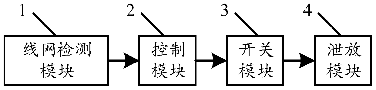
[0033] For details, please refer to figure 1 , figure 1 It is a block diagram of the self-adaptive discharge control circuit of this embodiment.

[0034] Such as figure 1 As shown, an adaptive discharge control circuit includes a line network detection module 1, a control module 2, a switch module 3 and a discharge module 4;

[0035] The line network detection module 1 is used to detect the line network voltage;

[0036] The control module 2 is connected to the line network detection module 1, and is used to receive and generate a discharge control signal according to the line network voltage, wherein the discharge control signal includes discharge duration information;

[0037] The switch module 3 is connected with the control module 2 and the relief module 4, and is used to receive the relief control signal, and output a switch signal to the relief module 4 according to the relief control signal. 4 performing switch control, so that the discharge duration information cor...


PUM


Abstract

The embodiment of the invention discloses a self-adaptive discharge control circuit and method. The circuit comprises a wire network detection module, a control module, a switch module, and a discharge module, wherein the wire network detection module is used for detecting the voltage of a wire network; the control module is connected with the wire network detection module and used for receiving and generating a discharge control signal according to the wire network voltage, and the discharge control signal comprises discharge duration information; and the switch module is connected with the control module and the discharge module and is used for receiving the discharge control signal and outputting a switch signal to the discharge module according to the discharge control signal to perform switch control on the discharge module, so that the discharge duration information corresponds to the opening time of the discharge module. According to the embodiment of the invention, the openingtime of the silicon controlled rectifier is controlled by controlling the opening time of the discharge module, so that an LED dimming function is realized, and the situation in which the system efficiency is reduced due to the fact that a discharge current path is normally opened is avoided.

Description

technical field [0001] Embodiments of the present invention relate to the technical field of power electronics, in particular to an adaptive bleeding control circuit and method. Background technique [0002] Thyristor dimming is a commonly used dimming method. The thyristor dimmer adopts the phase control method to realize dimming, that is, the conduction of the thyristor dimmer is controlled every half cycle of the sine wave to obtain the same conduction phase angle. By adjusting the chopping phase of the thyristor dimmer, the conduction phase angle can be changed to realize dimming. [0003] In the control system of the electronic circuit, when the thyristor is connected, when the thyristor is turned on, the minimum holding current is required to maintain the normal opening of the thyristor. If the current of the system is less than the minimum holding current, the thyristor will be damaged. Closed, when the line network voltage is lower than the LED conduction voltage, ...

Claims


Application Information

Patent Timeline
Patent Type & Authority Applications(China)
IPC IPC(8): H05B33/08H05B44/00
CPCY02B20/30
Inventor 郭伟峰郭东剑李照华
Owner SHENZHEN SUNMOON MICROELECTRONICS
Why Eureka
Try Eureka