
scroll compressor

A scroll compressor and scroll technology, applied in the field of compressors, can solve problems such as the rigidity of the scroll part without specific consideration, and achieve the advantages of preventing deformation or rupture, friction loss or wear improvement, and improving efficiency and reliability. Effect

Active Publication Date: 2022-03-01
LG ELECTRONICS INC
View PDF8 Cites 0 Cited by
  • Summary
  • Abstract
  • Description
  • Claims
  • Application Information

AI Technical Summary

Problems solved by technology

The resulting problem can be seen as arbitrarily changing the shape of the wrap without specifically considering the rigidity of the wrap

Method used


Image

  • scroll compressor
  • scroll compressor
  • scroll compressor

Examples


Embodiment Construction

[0047] Hereinafter, the scroll compressor of the present invention will be described in detail with reference to an embodiment shown in the accompanying drawings. However, for convenience of explanation, a typical example of a lower compression type scroll compressor in which the rotating shaft and the orbiting wrap overlap on the same plane in which the compression portion is located below the transmission portion will be described below. This type of scroll compressor is known to be suitable for refrigeration cycles under high temperature and high compression ratio conditions.

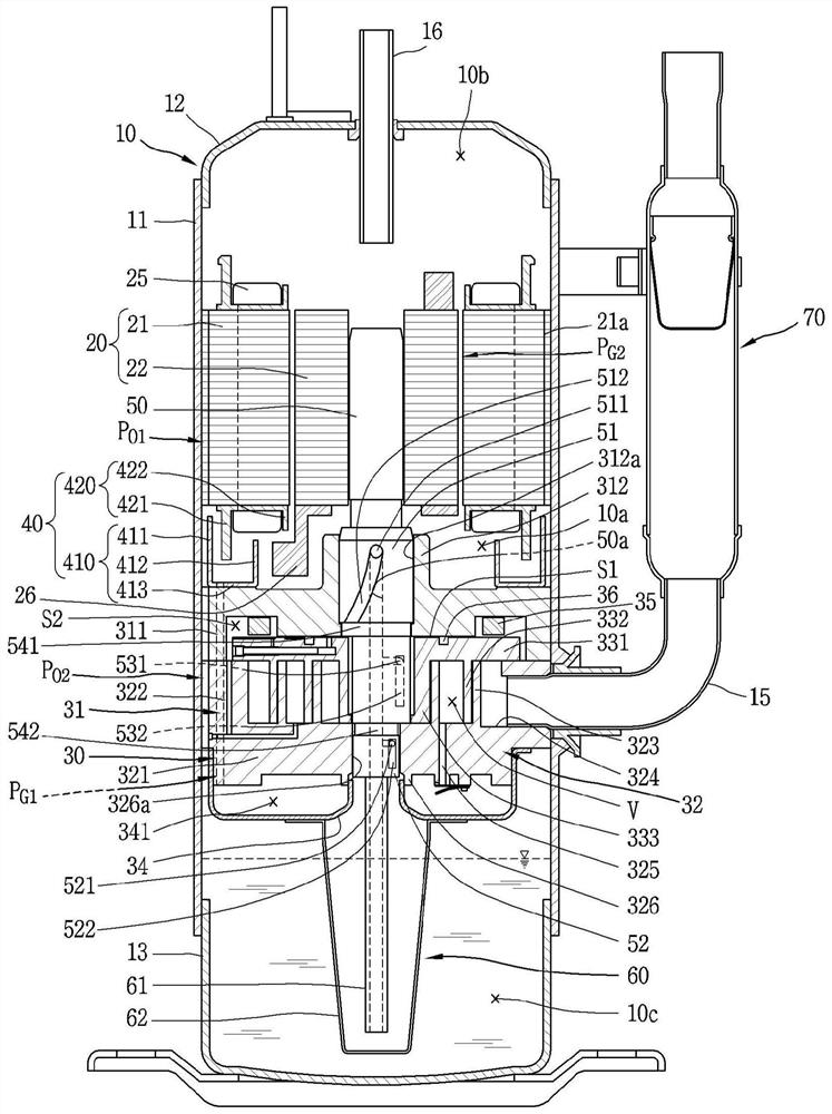
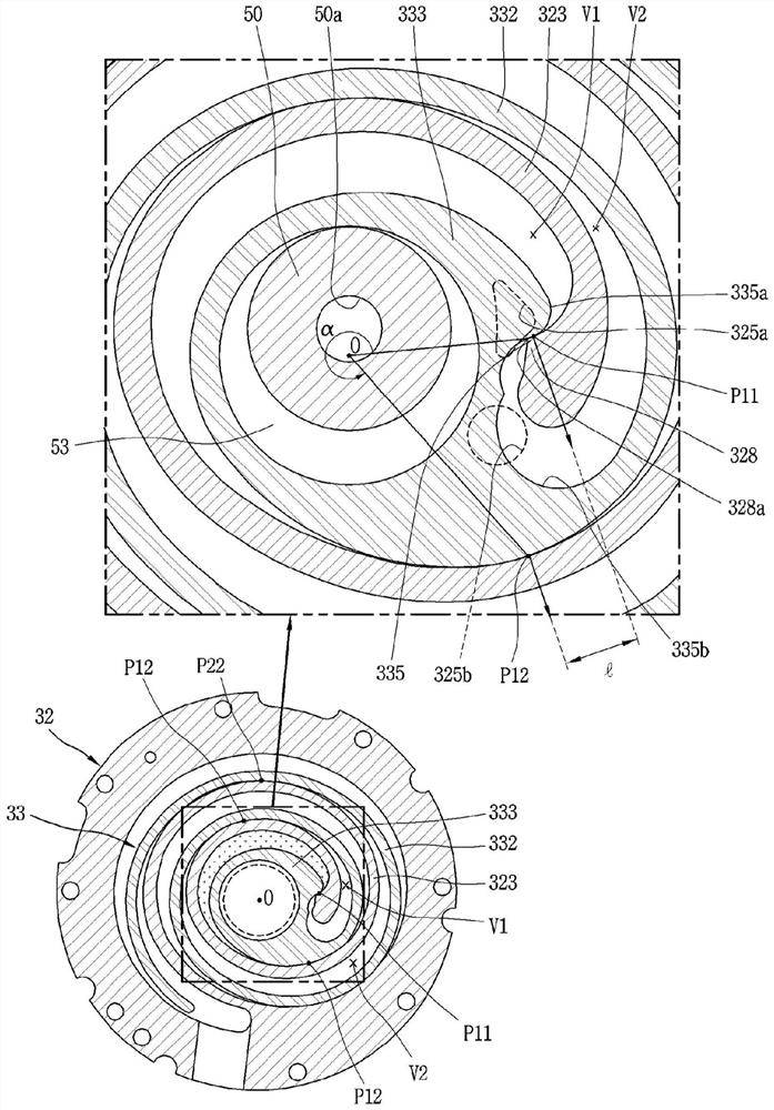
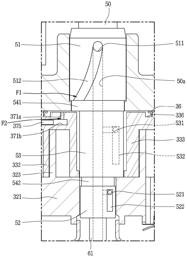
[0048] figure 1 It is a longitudinal sectional view showing the lower compression type scroll compressor of the present invention. figure 2 yes means figure 1 Transverse sectional view of the compression section in . image 3 is to illustrate figure 1 The front view of a part of the rotating shaft is shown as the sliding part in the figure. Figure 4 is to illustrate figure 1 A longitudinal se...


PUM


Abstract

The scroll compressor of the present invention includes: a first scroll, including a first end plate portion and a first scroll portion, the first end plate portion is formed with a support hole through which the rotating shaft penetrates at the center, and A discharge port is formed around the support hole, the first scroll portion protrudes from one side of the first end plate portion; and the second scroll includes a second end plate portion and a second scroll portion. The second end plate part is formed with a rotating shaft coupling part at the center for eccentric coupling of the rotating shaft penetrating through the bearing hole of the first scroll, and the second scroll part is formed on the second scroll part. One side surface of the two end plate parts protrudes and is engaged with the first scroll part to form a compression chamber. The first scroll part is formed so that the rigidity coefficient defined as follows is 0.005 / mm or more. The stiffness coefficient is defined as the reciprocal of the value obtained by dividing the wrap height of the first wrap by the wrap thickness and multiplying this value by the radius of curvature of the first wrap. Therefore, by suppressing deformation of the wrap portion, frictional loss and wear can be prevented, and damage to the wrap portion can be prevented.

Description

technical field [0001] The invention relates to a scroll compressor, in particular to a compressor in which the compression part is arranged on one side of the transmission part. Background technique [0002] A scroll compressor is a compressor in which a plurality of scrolls engage to perform relative orbital motion, and a compression chamber composed of a suction chamber, an intermediate pressure chamber, and a discharge chamber is formed between the scrolls on both sides. This type of scroll compressor can achieve a relatively high compression ratio compared with other types of compressors, and can obtain stable torque because the suction, compression, and discharge strokes of the refrigerant can be smoothly performed. Therefore, scroll compressors are widely used for refrigerant compression in air conditioners and the like. Recently, high-efficiency scroll compressors with reduced eccentric loads and operating speeds above 180 Hz have been introduced. [0003] The scro...

Claims


Application Information

Patent Timeline
Patent Type & Authority Patents(China)
IPC IPC(8): F04C18/02
CPCF04C18/02F04C18/0215F04C18/0284
Inventor 崔龙揆崔重善金哲焕
Owner LG ELECTRONICS INC
Learn More