Ampoule bottle breaking device

A technology of breaker and ampoules, which is applied in the directions of bottle/container cap, bottle filling, opening and closing containers, etc., can solve the problems of inability to sterilize ampoules, particles easily entering the bottle, and easily generating debris, etc. The number of hand changes, the structure is simple, and the effect of avoiding pollution

Inactive Publication Date: 2019-12-20
陈小克
View PDF12 Cites 0 Cited by
  • Summary
  • Abstract
  • Description
  • Claims
  • Application Information

AI Technical Summary

Problems solved by technology

[0003] The purpose of the present invention is to overcome the problems of the existing ampoule bottle opening device, such as complex structure, inconvenient bottle opening, easy hand injury, inability to effectively sterilize the ampoule bottle, easy generation of debris, and easy entry of particles into the bottle to cause safety hazards. The ampoule bottle breaker includes splints connected at the upper ends, and the opposite surfaces of the two splints are clamping surfaces; the lower end of the clamping surface of at least one of the splints is embedded with a crescent-shaped grinding wheel or the clamping surface of at least one of the splints The lower end is provided with protrusions for wearing hard objects

Method used


Image

  • Ampoule bottle breaking device
  • Ampoule bottle breaking device
  • Ampoule bottle breaking device

Examples


Embodiment 1

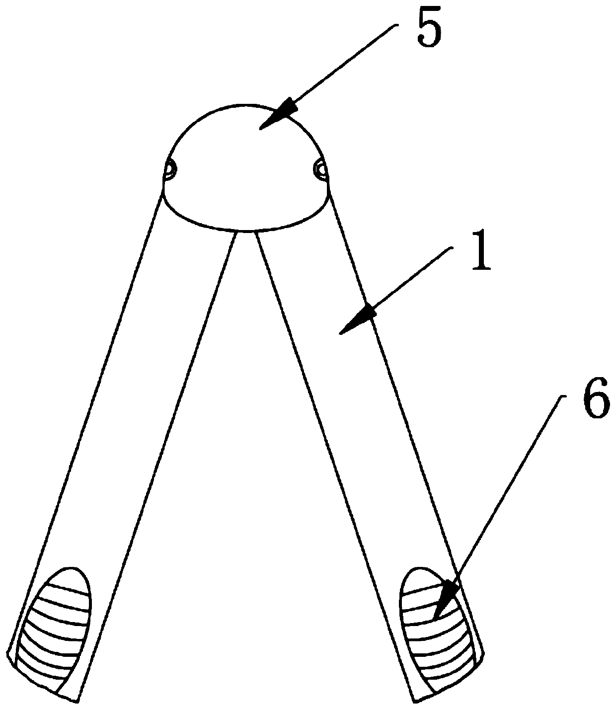
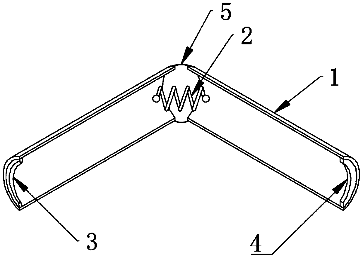
[0022] Such as figure 1 , 2 1. The ampoule breaker shown in 3 includes splints 1 connected at the upper ends, and the opposite surfaces of the two splints 1 are clamping surfaces; at least one of the clamping surfaces of the splints 1 is embedded with a crescent-shaped grinding wheel 3 or at least The lower end of the clamping surface of one of the splints 1 is provided with a protrusion for wearing hard objects (such as glass ampoules). In this embodiment, a crescent-shaped grinding wheel 3 is embedded in the inner wall of the lower end of one splint 1 , and a sponge or composite material 4 is installed at the lower end of the other splint 1 opposite to the grinding wheel 3 .

[0023] The inner walls at the upper ends of the two splints 1 are connected by a spring 2 . The upper ends of the two splints 1 are also covered with hinged caps 5; both sides of the hinged caps 5 are hinged to the two splints 1 respectively.

[0024] In this embodiment, the clamping surface or the ...

Embodiment 2

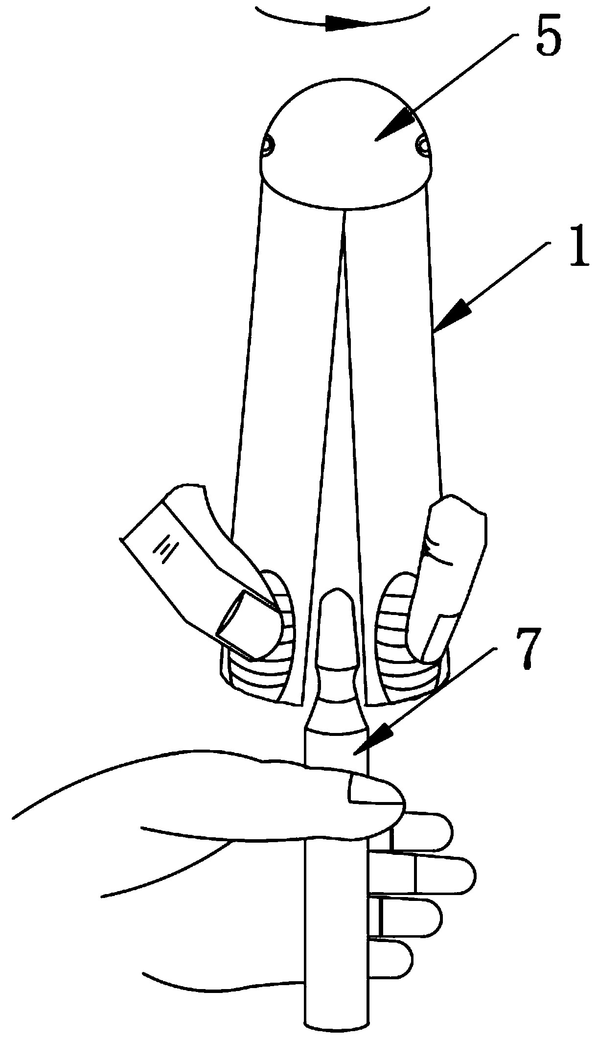
[0029] Such as Figure 4 As shown, the structure of the ampoule breaker of the present embodiment 2 is substantially the same as that of the embodiment 1, the difference is that the upper ends of the two splints 1 are hinged; a hinged cap 5 covering the upper ends of the two splints 1 is also included; the two splints The upper ends of 1 are respectively connected to two opposite inner walls of the hinge cap 5 through a spring 2 . The difference between this embodiment and embodiment 1 is that two springs 2 are provided, and each splint 1 corresponds to a spring 2 connected to the hinged cap 5. This design makes the clamping times of the breaker more, and the spring 2 wears less. Small, more durable, and the two splints 1 are in the normal open state. When in use, align the neck of the ampoule 7 and clamp the two splints 1 to rotate at least one turn before breaking the ampoule 7. At this time, clamp The splint 1 clamps the part above the neck of the ampoule 7, and the breake...

Embodiment 3

[0031] Such as Figure 5 As shown, the structure of the ampoule breaker in Embodiment 3 and Embodiment 2 is roughly the same, the difference is that the hinged cap 5 and the spring 2 are removed; the upper ends of the two splints 1 are directly connected as one or the two splints 1 are directly integrally formed. ; The splint 1 is a splint made of elastic material, and the junction of the upper ends of the splint 1 is provided with a protrusion 8 for keeping the two splints 1 apart. The protrusions 8 of the two splints 1 are arranged opposite to each other.


PUM


Abstract

The invention discloses an ampoule bottle breaking device. The device comprises two clamping plates connected at the upper ends, wherein the opposite surfaces of the two clamping plates are clamping surfaces, a crescent grinding wheel is embedded at the lower end of the clamping surface of the at least one clamping plate, and sponge or a composite material is arranged at the position, opposite tothe grinding wheel, of the lower end of the other clamping plate. The ampoule bottle breaking device is highly integrated in function, the number of hand changing of medical workers is reduced, the working efficiency is improved, generation of glass chips can be effectively avoided, particles can be prevented from entering an ampoule bottle, and risks are reduced, and the ampoule bottle breaking device is simple in structure, low in cost, simple and convenient to use, capable of being recycled, and convenient to clean and disinfect.

Description

technical field [0001] The invention relates to the technical field of medical instruments, in particular to an ampoule breaker. Background technique [0002] At present, many liquid medicines are packed in glass ampoules. In order to quickly open the ampoule, medical personnel usually use the method of directly breaking the neck of the ampoule by hand or using an ampoule bottle opener; directly breaking the neck of the ampoule by hand The way is very easy to hurt the hand; the existing ampoule bottle opener has many different types, the structure is complex but the function is single, such as one side of a handle is horizontally provided with a grinding wheel, and the ampoule bottle neck is sawed or cut or cut by the grinding wheel. Cut open (hereinafter referred to as sawing) a section of opening, and then break it off by hand. This method makes it easier for medical staff to open the ampoule bottle, but there is only one section of opening, and the force on the neck of th...

Claims


Application Information

Patent Timeline
IPC IPC(8): B67B7/92
CPCB67B7/92
Inventor 陈小克陈燕陈萍
Owner 陈小克
Why Eureka
Try Eureka