
A universal-multistage energy-dissipating beam-column joint sealing damper and its installation method

A technology of beam-column joints and dampers, which is applied in the direction of building types, buildings, and building components, can solve the problems of inability to achieve multi-level energy consumption, high maintenance costs of dampers, and damage of dampers, and achieve simple structure and low cost. Inexpensive, easy-to-use effect

Inactive Publication Date: 2020-11-03
黑龙江省地震办公室
View PDF8 Cites 0 Cited by
  • Summary
  • Abstract
  • Description
  • Claims
  • Application Information

AI Technical Summary

Problems solved by technology

[0007] At present, domestic node corner dampers are mainly installed at the positions of building beam-column joints and can only dissipate energy in the longitudinal direction, while building beam-column joints undergo longitudinal and transverse relative rubbing at the same time during actual earthquake action, and traditional dampers use shear Cutting lead rods, twisting and breaking deformation to dissipate the energy of earthquake response and wind vibration, the damper may be damaged after a major earthquake, and multi-level energy consumption cannot be achieved
In addition, the maintenance cost of replacing the damper after the earthquake is high, and it is easy to cause waste of materials
At present, there is no universal-multi-stage energy-dissipating beam-column joint sealing damper at home and abroad

Method used


Image

  • A universal-multistage energy-dissipating beam-column joint sealing damper and its installation method
  • A universal-multistage energy-dissipating beam-column joint sealing damper and its installation method
  • A universal-multistage energy-dissipating beam-column joint sealing damper and its installation method

Examples


Embodiment Construction

[0032] Exemplary embodiments of the present disclosure will be described in more detail below with reference to the accompanying drawings, these embodiments are for a more thorough understanding of the present invention and can fully convey the scope of the present disclosure to those skilled in the art. While the drawings show exemplary embodiments of the present disclosure, it is to be understood that the invention is not to be limited to the embodiments set forth herein.

[0033] In describing the present invention, it should be understood that the terms "longitudinal", "transverse", "upper", "lower", "front", "rear", "left", "right", "vertical", The orientations or positional relationships indicated by "horizontal", "top", "bottom", "inner", "outer", etc. are based on the orientations or positional relationships shown in the drawings, and are only for the convenience of describing the present invention, rather than indicating or It should not be construed as limiting the i...


PUM


Abstract

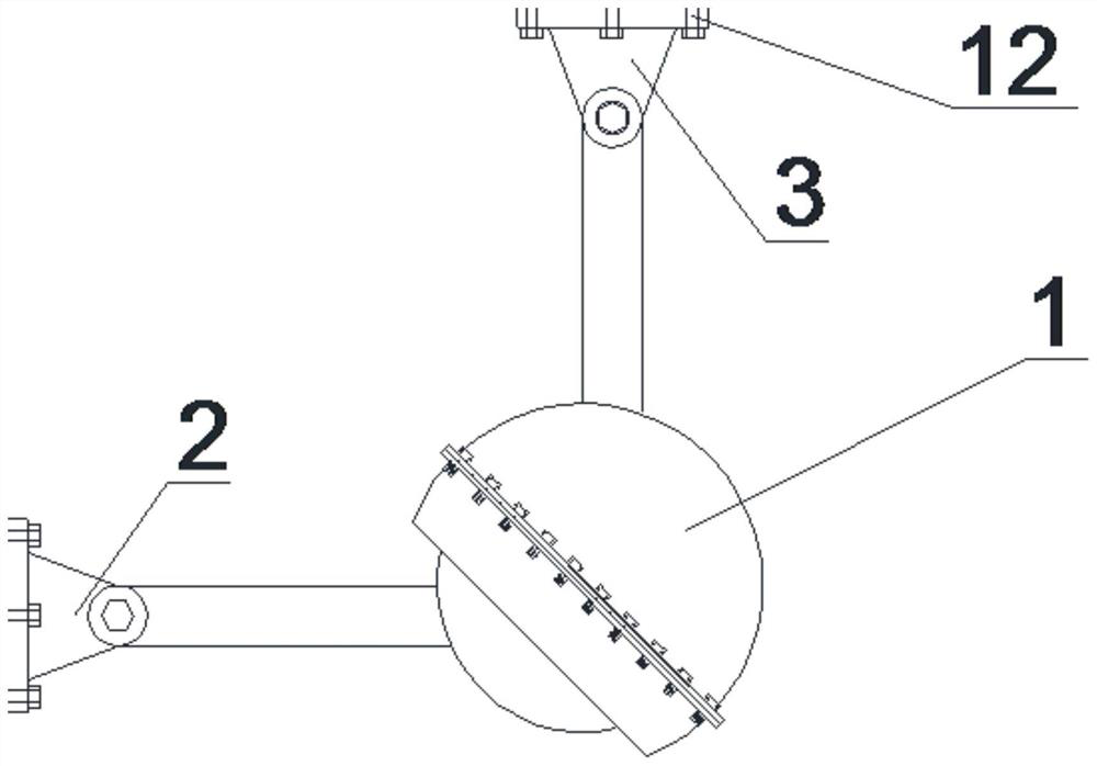
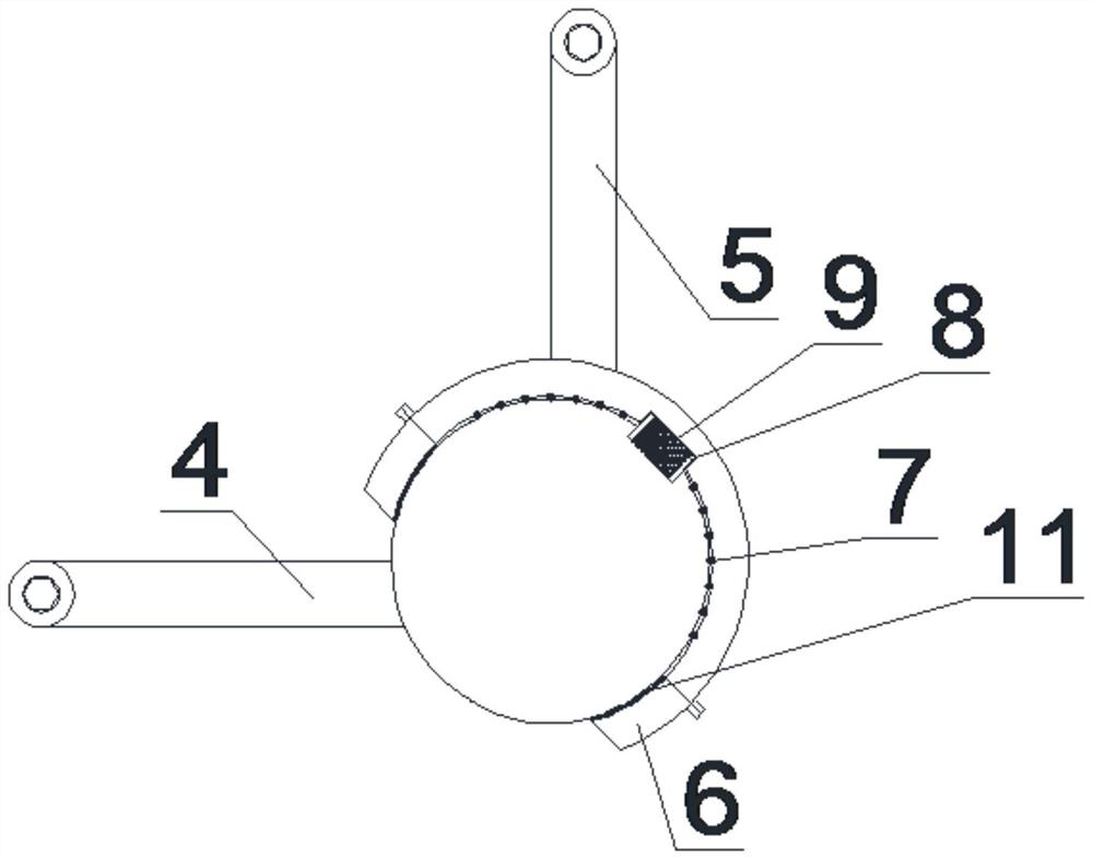
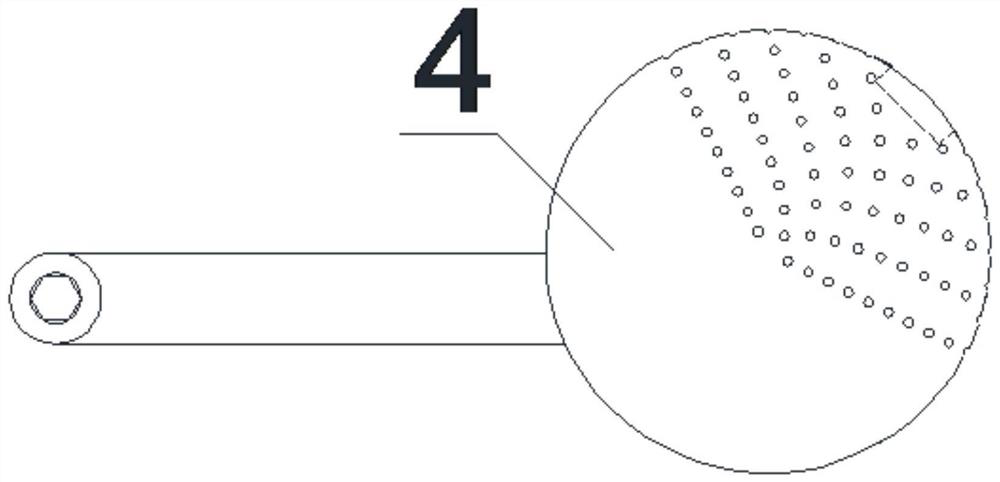
The invention discloses an universal-multi-stage energy consumption beam column node sealing damper and a mounting method. The damper comprises an universal energy consumption body, a column hinge bracket and a beam hinge bracket. The universal energy consumption body is of a spherical structure provided with a loading arm; and the column hinge bracket and the beam hinge bracket are fixedly arranged at the upper and lower ends of the universal energy consumption body. The column hinge bracket is in bolt connection with an universal loading ball loading arm of the universal energy consumption body; a column hinge bracket fixed plate is provided with an anchoring mounting port; and the column hinge bracket is anchored with a column end through the anchoring mounting port. The beam hinge bracket is in bolt connection with a loading fixed half-ball shell loading arm of the universal energy consumption body; a beam hinge bracket fixed plate is provided with an anchoring mounting port; and the beam hinge bracket is anchored with a beam end through the anchoring mounting port. The damper has the advantage of repeated use; and the universal energy consumption body can be opened after vibration to replace such energy consumption elements as a soft steel energy consumption ball, a high-damping rubber cylinder and a memory alloy axis rod, so that the problems of once use, high maintenancecost and easy waste of materials and dampers in traditional dampers are solved.

Description

technical field [0001] The invention relates to an earthquake damping device, in particular to a universal-multistage energy-dissipating beam-column node sealing damper and an installation method, which belong to the technical field of damping and energy consumption. Background technique [0002] Among the provincial capital cities of my country's 34 administrative regions, at least 21 cities have active seismic faults and potential dangers of near-field strong earthquakes; more than 2,000 cities and towns across the country are always facing the threat of catastrophic earthquakes. There is a clear contradiction between the demand for safety in the rapid economic development and the threat of severe earthquake disasters faced by the majority of cities in our country. Property damage exacerbated this contradiction. [0003] The traditional joint seismic design method is too passive, mainly relying on increasing the section size of the column or increasing the reinforcement o...

Claims


Application Information

Patent Timeline
Patent Type & Authority Patents(China)
IPC IPC(8): E04B1/98E04H9/02
CPCE04H9/021
Inventor 孙海峰杜秋男杜天然张立忱王丽梅欧阳兆国
Owner 黑龙江省地震办公室
Learn More