Concrete beam form supporting device and construction process thereof

A formwork support and concrete beam technology, which can be applied to formwork/formwork/work frame, connection parts of formwork/formwork/work frame, on-site preparation of building components, etc., can solve the lack of effective oblique support on the side, installation Difficulties, beam formwork expansion and other problems, achieve the effect of realizing multiple turnover and reuse, reducing construction costs, and solving the problem of slurry leakage

Pending Publication Date: 2019-12-20
TIANJIN 20 CONSTR
View PDF7 Cites 2 Cited by
  • Summary
  • Abstract
  • Description
  • Claims
  • Application Information

AI Technical Summary

Problems solved by technology

[0002] The traditional 200mm, 300mm wide and no more than 500mm high beam lower side formwork is mostly supported by steel pipes or steel clamps, and the side lacks effective oblique support, which makes the side of the beam formwork prone to expansion and the bottom.
Due to the small cross-sectional area of ​​the beam, when using prefabricated clips, they need to be set according to the size respectively, which cannot be adjusted. The demand for materials is large, and it is too dependent on the fixed size. For beams with deviations, the adjustable range is narrow, difficult to install, and the fixing effect poor

Method used


Image

  • Concrete beam form supporting device and construction process thereof
  • Concrete beam form supporting device and construction process thereof
  • Concrete beam form supporting device and construction process thereof

Examples


Embodiment Construction

[0037] Below in conjunction with embodiment and accompanying drawing, the present invention will be further described:

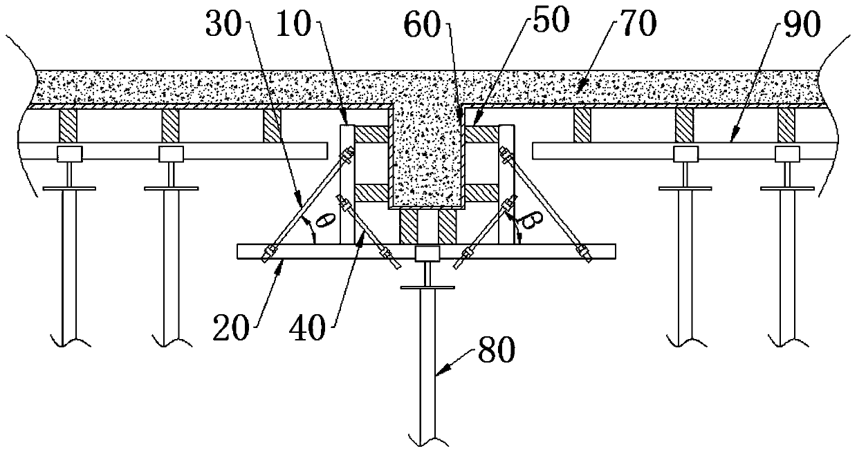
[0038] In the interior structure of housing construction projects, such as figure 1 As shown, there are often downward protruding beams in the roof of the house. The cross section of the beams is relatively small, the height generally does not exceed 500mm, and the width is between 200-300mm. However, during the construction process, the beam formwork 60 needs to be built in advance, so that the internal structure of the beam formwork 60 is compatible with the outer wall structure of the house beam. Horizontal top templates 70 are also provided on both sides of the beam template 60 of the house beam, and the top template 70 is integrally connected with the beam template 60 . Before actually pouring concrete, the top formwork 70 is fixed on the crossbeam 90 through the wooden square 50, and the crossbeam 90 is fixed on the scaffold 80. If the beam formwork ...


PUM


Abstract

The invention provides a concrete beam form supporting device and a construction process thereof. The concrete beam formwork supporting device comprises positioning parts, a supporting part, fixing parts and clamping parts, wherein the positioning parts, the fixing parts and the clamping parts are all symmetrically arranged at the two outer side surfaces of the cross section of a beam form, and the supporting part is arranged below the beam form and is parallel to the width direction of the beam form; the positioning parts are arranged close to the beam form, and are arranged above the supporting part; the fixing parts are arranged on the outer sides of the positioning parts, and the two ends of each fixing part are connected with one positioning part and the supporting part correspondingly; the clamping parts are arranged on the inner sides of the positioning parts, and the two ends of each clamping part are connected with one positioning part and the supporting part correspondingly;the clamping parts are obliquely arranged relative to the supporting part, and the positions of joints between the fixing parts and the positioning parts are higher than the positions of joints between the clamping parts and the positioning parts; and the positions of joints between the fixing parts and the supporting part are far away from the beam form, and the positions of joints between the clamping parts and the supporting part are close to the beam form. According to the concrete beam form supporting device, the supporting device has the advantages of being simple in structure, easy to control, high in universality, reusable and low in cost.

Description

technical field [0001] The invention belongs to the technical field of residential project construction engineering, and in particular relates to a concrete beam formwork support device and a construction process thereof. Background technique [0002] The traditional 200mm, 300mm wide and not more than 500mm high beam lower side formwork is mostly supported by steel pipes or steel clamps, and the side lacks effective oblique support, which makes the beam formwork prone to mold swelling on the side and grout leakage at the bottom. Due to the small cross-sectional area of ​​the beam, when using prefabricated clips, they need to be set according to the size respectively, which cannot be adjusted. The demand for materials is large, and it is too dependent on the fixed size. For beams with deviations, the adjustable range is narrow, difficult to install, and the fixing effect poor. Contents of the invention [0003] The problem to be solved by the present invention is to provi...

Claims


Application Information

Patent Timeline
Patent Type & Authority Applications(China)
IPC IPC(8): E04G13/04E04G17/00
CPCE04G13/04E04G17/00
Inventor 刘江李涛
Owner TIANJIN 20 CONSTR
Why Eureka
Try Eureka