
Compound pendulum frequency upconversion type wave energy collecting device

A technology of collecting device and wave energy, applied in electromechanical devices, controlling mechanical energy, ocean energy power generation, etc., can solve the problems of low energy capture efficiency, single, low energy conversion efficiency, etc

Pending Publication Date: 2019-12-20
SUZHOU UNIV
View PDF0 Cites 15 Cited by
  • Summary
  • Abstract
  • Description
  • Claims
  • Application Information

AI Technical Summary

Problems solved by technology

However, the energy harvesting efficiency of the existing inertial energy harvesting mechanism working at extremely low frequencies is generally not high, and the output power density of the device is low
Moreover, the electromechanical coupling energy conversion mechanism adopted by the existing miniature wave energy harvesting devices is relatively simple, and only one of electromagnetic conversion, piezoelectric conversion or friction power generation is used, and the adaptability to ocean wave energy is not strong. low efficiency

Method used


Image

  • Compound pendulum frequency upconversion type wave energy collecting device
  • Compound pendulum frequency upconversion type wave energy collecting device
  • Compound pendulum frequency upconversion type wave energy collecting device

Examples


Embodiment Construction

[0027] The following will clearly and completely describe the technical solutions in the embodiments of the present invention with reference to the accompanying drawings in the embodiments of the present invention. Obviously, the described embodiments are only some, not all, embodiments of the present invention. Based on the embodiments of the present invention, all other embodiments obtained by persons of ordinary skill in the art without making creative efforts belong to the protection scope of the present invention.

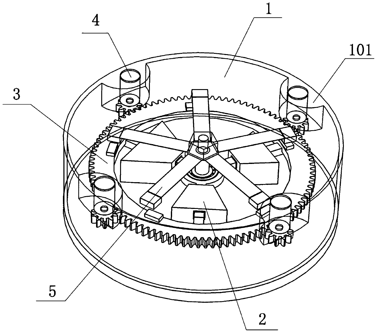
[0028] Please refer to figure 1 , figure 1 It is a schematic diagram of the overall structure of a specific embodiment provided by the present invention.

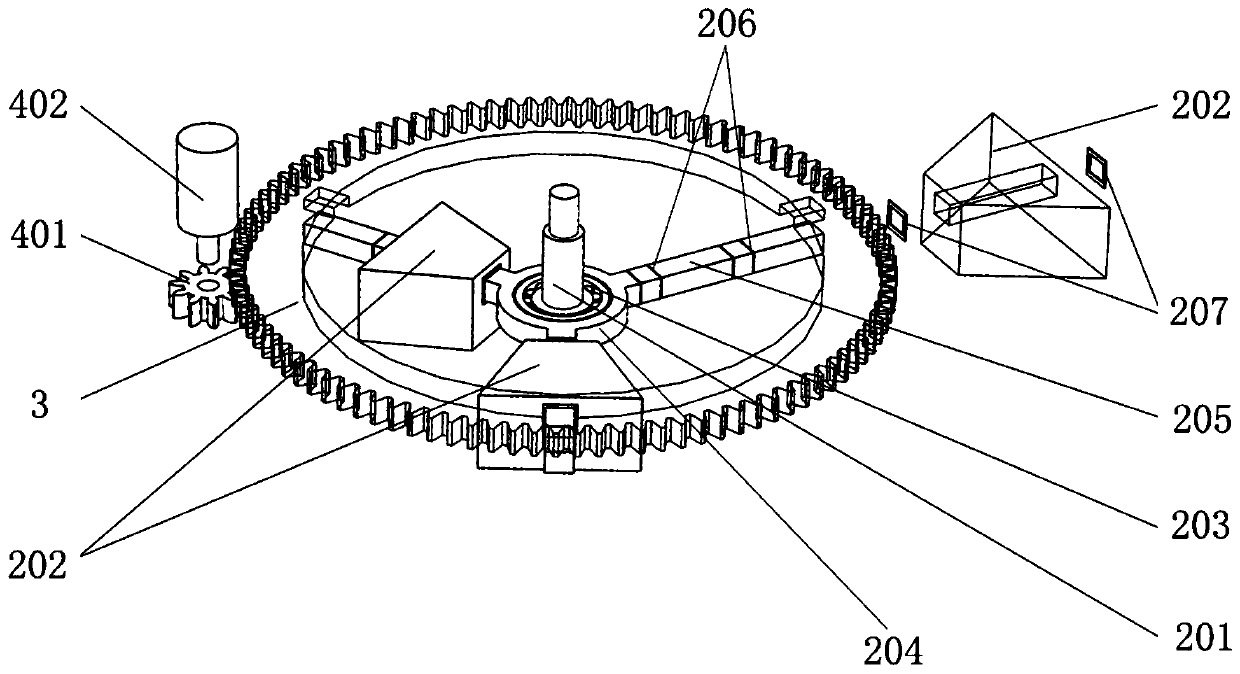
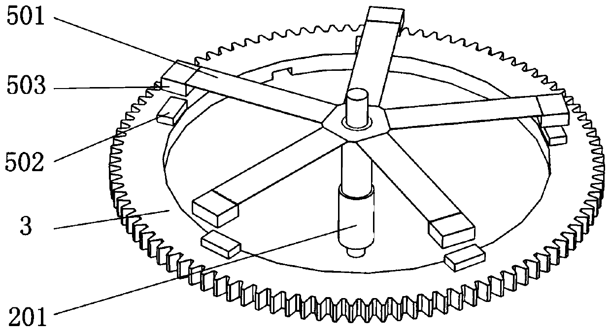
[0029] In a specific embodiment provided by the present invention, the compound swing up-frequency wave energy harvesting device mainly includes a housing 1 , a compound swing mechanism 2 , a driving gear 3 , an electromagnetic generating mechanism 4 and a piezoelectric generating mechanism 5 .

[0030]Am...


PUM


Abstract

The invention discloses a compound pendulum frequency upconversion type wave energy collecting device. The compound pendulum frequency upconversion type wave energy collecting device comprises a shell, a compound pendulum mechanism, a driving gear, an electromagnetic power generating mechanism and a piezoelectric power generating mechanism. The shell floats on the water surface and swings along with waving, the compound pendulum mechanism is rotationally arranged in the shell and rotates along with swinging of the shell, and driving gear is rotationally arranged in the shell, and the driving gear and the compound pendulum mechanism rotate synchronously. The electromagnetic power generating mechanism is arranged in the shell and used for being in engaged transmission with the driving gear to be driven by the driving gear to generate power through electromagnetic induction. The piezoelectric power generating mechanism is arranged in the shell and located above the end face of the drivinggear and is used for generating deformation to generate power through a piezoelectric effect when the driving gear rotates. Thus, when the shell non-directionally swings along with waving, the compound pendulum mechanism generates non-directional rotation and adapts to dynamic changes of water surface wave energy, and high energy harvesting efficiency is achieved. Meanwhile, the electromagnetic power generating mechanism and the piezoelectric power generating mechanism carry out energy conversion through two different electromechanical coupling energy exchange mechanisms, the spectrum coverage range on wave energy is wide, high adaptability is achieved, and the conversion efficiency is high.

Description

technical field [0001] The invention relates to the technical field of power generation, in particular to a compound swing up-frequency wave energy collection device. Background technique [0002] At present, marine environmental observation mainly uses various marine observation equipment and systems for fixed-point platform observation and mobile three-dimensional network observation, such as general-purpose and special-purpose ocean data buoys equipped with multi-parameter sensors, Lagrangian drifting buoys, etc. These ocean observation equipments have long-term mobile operation and carry a variety of sensors. While generating a large amount of data, they also need to consume a large amount of energy. It is far from enough to carry high-capacity batteries and reduce energy consumption. When necessary, energy must be obtained from the marine environment or fed back from the system to ensure the long-term operation of the system. [0003] The ocean covers about 71% of the ...

Claims


Application Information

Patent Timeline
Patent Type & Authority Applications(China)
IPC IPC(8): F03B13/14H02K7/18H02N2/18
CPCF03B13/14H02K7/1846H02N2/186F05B2220/706F05B2260/4031Y02E10/30H02K7/1853H02K7/116H02K1/2793H02K5/1735H02K5/15F03B13/20F05B2250/44F05B2260/407F05B2250/72H02N2/18H10N30/306F03B13/16
Inventor 刘会聪黄曼娟李云飞陈涛孙立宁
Owner SUZHOU UNIV
Learn More