Supercharge Your Innovation With Domain-Expert AI Agents!

A driving structure of a three-shaft multi-stage Roots pump

A driving structure, the technology of Roots pump, which is applied to the sealing device of the piston pump, the components of the pumping device for elastic fluid, the pump, etc., can solve the problem of low rotor meshing degree, complex driving structure, large cumulative error, etc. problems, to achieve the effect of improving stability, improving sealing efficiency, and strengthening rigidity

Active Publication Date: 2021-05-25
兑通真空技术(上海)有限公司
View PDF0 Cites 0 Cited by
  • Summary
  • Abstract
  • Description
  • Claims
  • Application Information

AI Technical Summary

Problems solved by technology

[0003] However, the driving structure of the existing three-axis multi-stage Roots pump is relatively complicated. Each stage of the pump cavity adopts three independent shafts. The key realizes concentric and synchronous rotation, and each independent shaft is limited by fixed bearings, so that the shafts in different stages of pump chambers are independent of thermal expansion displacement
In actual operation, due to the large number of parts and complex structure, the cumulative error is very large and cannot be eliminated, resulting in low engagement of the rotors in the multi-stage pump chamber, which is easy to cause rubbing, and each independent axis needs Fixed bearing limit, too many bearings, when rotating at high speed, there will be a lot of noise
Moreover, the shafts between different series are nested through the mother and child, so the strength is not enough, and the torque transmission between the mother shaft and the child shaft is easy to cause the root of the child shaft to break

Method used


Image

  • A driving structure of a three-shaft multi-stage Roots pump
  • A driving structure of a three-shaft multi-stage Roots pump
  • A driving structure of a three-shaft multi-stage Roots pump

Examples


Embodiment Construction

[0025] In order to make the purpose, technical solutions and advantages of the present invention clearer, the technical solutions in the present invention will be clearly and completely described below in conjunction with the accompanying drawings in the present invention.

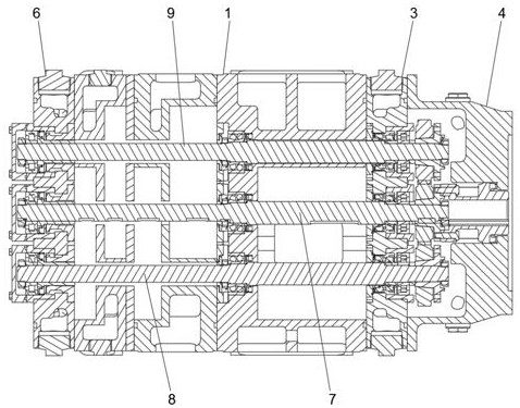
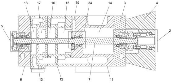
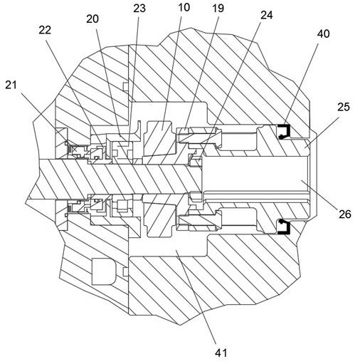
[0026] Such as Figure 1-5As shown, a driving structure of a three-axis multi-stage Roots pump includes a pump body 1, and one side of the pump body 1 is equipped with a gear mechanical seal drive unit 2 at the intake end, and the outer surface of the gear mechanical seal drive unit 2 at the intake end A gear end cover 3 is installed, and the gear end cover 3 is fixedly installed on the side end surface of the pump body 1. The outer surface of the gear end cover 3 is fixedly installed with a motor connection seat 4, and the other side of the pump body 1 is installed with a moving bearing at the exhaust end. Air seal unit 5, the outer surface of the air seal unit 5 is equipped with a moving bearing at the e...


PUM


Abstract

A driving structure of a three-axis multi-stage Roots pump, including a pump body, a gear end cover installed on one side of the pump body, a moving bearing air seal unit at the exhaust end installed on the other side of the pump body, and a bearing end cover installed on the pump body The side of the body; the inside of the pump body is also provided with a driving shaft, a first driven shaft and a second driven shaft, and the driving shaft is respectively connected to the first driven shaft and the second driven shaft through gears; the driving shaft, the first Both ends of the driven shaft and the second driven shaft are respectively movably connected in the gear mechanical seal drive unit at the intake end and the mobile bearing air seal unit at the exhaust end. The invention overcomes the deficiencies of the prior art. The fixed bearing limiting unit not only acts as a radial support, but also strengthens the rigidity of the independent shaft, and can reduce the diameter of the shaft. The end is evenly carried out, avoiding deformation in a single direction, and reducing the displacement by nearly half. At the same time, the sealing efficiency of the system is improved.

Description

technical field [0001] The invention relates to the technical field of driving a Roots pump, in particular to a driving structure of a three-axis multistage Roots pump. Background technique [0002] The three-shaft multi-stage Roots pump is a new oil-free dry vacuum pump. There are three parallel shafts in each pump chamber. The three pump shafts rotate at the same speed, and the middle pump shaft is adjacent to the left pump shaft and the other. The adjacent right pump shafts rotate in the opposite direction; each stage of the pump chamber is equipped with a pair of rotors, and the paired rotors of the odd-numbered pump chambers are respectively connected to the middle pump shaft and its adjacent left pump shaft. The paired rotors of the first-stage pump chambers are respectively connected to the middle pump shaft and its adjacent right pump shaft. Thus, a unique airflow channel is formed, that is, the lower ports of the adjacent pump chambers are respectively the exhaust ...

Claims


Application Information

Patent Timeline
Patent Type & Authority Patents(China)
IPC IPC(8): F04C29/00F04C29/02F04C25/02F04C18/12F04C23/00F04C27/00
CPCF04C29/0042F04C29/02F04C25/02F04C18/126F04C18/082F04C18/086F04C23/001F04C27/00F04C2240/50F04C2240/60F04C2240/605F04C15/0003F04C18/14F04C2240/30F04C2240/80F04C18/165
Inventor 荣易李悦沈淼乐
Owner 兑通真空技术(上海)有限公司
Features
  • R&D
  • Intellectual Property
  • Life Sciences
  • Materials
  • Tech Scout
  • Unparalleled Data Quality
  • Higher Quality Content
  • 60% Fewer Hallucinations
Learn More