
Three-in-one water pump

A three-in-one, water pump technology, applied in the direction of pumps, pump devices, pump components, etc., can solve the problems of increasing the economic cost of purchase and use, and achieve the effect of compact structure, wide range of use, and convenient movement

Pending Publication Date: 2019-12-20
XINGHUA ZHONGXING ELECTRIC APPLIANCE MFG CO LTD
View PDF0 Cites 0 Cited by
  • Summary
  • Abstract
  • Description
  • Claims
  • Application Information

AI Technical Summary

Problems solved by technology

[0004] Different water pumps need to be installed for different use situations and use environments, which increases the economic cost of use and purchase, etc.

Method used


Image

  • Three-in-one water pump
  • Three-in-one water pump
  • Three-in-one water pump

Examples


Embodiment 1

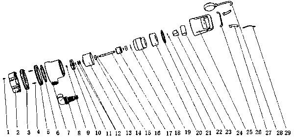
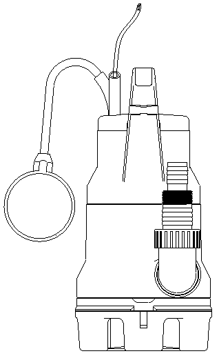
[0017] Such as figure 1 , figure 2 and image 3 A three-in-one water pump shown includes a first screw 1, a dirty base 2, a pump body 7, a rear pump casing 25 used in conjunction with each other, and a cleaning device arranged in the dirty base 2 and the pump body 7 and used in conjunction with each other. Base 3, second screw 4, base 5, first O-ring 6, lock nut 9, impeller 10, gasket 11, oil seal 12, Front cover 13, bearing 14, circlip 15, shaft 16, rotor core 17, three-peak washer 18, stator 19, back cover 20, second O-ring 21, snap button 22, back cover 23, capacitor 24, and A handle cover 26, a sheath 27, a floating stop 28, and an electrical cable 29 arranged on the rear pump casing 25.

Embodiment 2

[0019] Such as figure 1 , figure 2 and image 3 A three-in-one water pump shown includes a first screw 1, a dirty base 2, a pump body 7, a rear pump casing 25 used in conjunction with each other, and a cleaning device arranged in the dirty base 2 and the pump body 7 and used in conjunction with each other. Base 3, second screw 4, base 5, first O-ring 6, lock nut 9, impeller 10, gasket 11, oil seal 12, Front cover 13, bearing 14, circlip 15, shaft 16, rotor core 17, three-peak washer 18, stator 19, back cover 20, second O-ring 21, snap button 22, back cover 23, capacitor 24, and The handle cover 26, sheath 27, floating stop 28, cable 29 arranged on the rear pump casing 25, and the elbow joint 8 used in conjunction with the water outlet of the pump body 7.

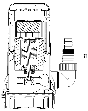
[0020] In the three-in-one water pump of Embodiment 1 or Embodiment 2 of this structure, the overall height dimension H of the sewage base 2, pump body 7, and rear pump casing 25 is 285.62-330mm.

[0021] The three-in-o...


PUM


Abstract

The invention belongs to the technical field of water pump application, and specifically discloses a three-in-one water pump. The three-in-one water pump comprises a first screw, a sewage base, a pumpbody, a rear pump casing, a clean base, a second screw, a base, a first O-shaped ring, a lock nut, an impeller, a gasket, an oil seal, a front cover, a bearing, a spring, a shaft, a rotor core, a three-peak washer, a stator, a rear cover, a second O-shaped ring, a pressure buckle, a back cover, a capacitor, a handle cover, a sheath, a float and a cable, wherein the first screw, the sewage base, the pump body, the rear pump casing, the clean base, the second screw, the base and the first O-shaped ring are cooperatively used; the lock nut, the impeller, the gasket, the oil seal, the front cover, the bearing, the spring, the shaft, the rotor core, the three-peak washer, the stator, the rear cover, the second O-shaped ring, the pressure buckle, the back cover and the capacitor are arranged inthe pump body and the rear pump casing and are cooperatively used; and the handle cover, a sheath, a float and a cable are arranged on the rear pump casing. The water pump has the beneficial effectsthat the water pump is reasonable in overall structure design and wide in application range, and can be used in the total lift range, a float switch arranged on the water pump can automatically control the pump to be turned on and off according to the change of the water level, automatic action can be achieved, meanwhile, the functions a sewage pump, a clean water pump and a low suction water pumpcan be achieved through the water pump, and switching between various water pump functions is convenient and can be achieved by removing a screw.

Description

technical field [0001] The invention belongs to the technical field of water pump applications, and in particular relates to a three-in-one water pump. Background technique [0002] The water pump is a kind of machinery for conveying liquid, which converts the mechanical energy of the prime mover into the pressure energy of the liquid. Before the centrifugal water pump works, the vortex cavity must be filled with water; when the impeller rotates, the liquid in the middle of the blade rotates with the blade, and under the action of centrifugal force, the liquid flies away from the impeller and shoots outward; a vacuum and low pressure are formed at the center of the impeller In the area, the liquid in the liquid pool flows into the impeller through the inlet of the pump under the action of the external atmospheric pressure; while the liquid ejected from the impeller accumulates in the vortex cavity, and the pressure gradually increases, so that the liquid is pressed out from ...

Claims


Application Information

Patent Timeline
Patent Type & Authority Applications(China)
IPC IPC(8): F04D13/06F04D29/42
CPCF04D13/0606F04D29/426
Inventor 贾中亮张永涛
Owner XINGHUA ZHONGXING ELECTRIC APPLIANCE MFG CO LTD
Learn More