Energy gathering disc with combustion function and gas stove comprising same

An energy-gathering plate and functional technology, applied in the field of kitchen utensils, can solve the problems of low heating efficiency and low gas combustion efficiency of gas stoves, and achieve the effects of ensuring stability and sufficiency, increasing heating range, and improving heating efficiency

Inactive Publication Date: 2019-12-20
NINGBO FOTILE KITCHEN WARE CO LTD
10 Cites 2 Cited by

AI-Extracted Technical Summary

Problems solved by technology

[0004] The technical problem to be solved by the present invention is to overcome the defects of low gas combustion efficiency and low heat...

Method used

Annular air mixing chamber 2 comprises the first side wall 21 that is connected with the introduction channel 5 and the second side wall 22 that is connected with the air outlet channel 4, the first side wall 21 is horizontally arranged, and the second side wall 22 is obliquely downward It is provided that the third side wall 23 opposite to the second side wall 22 is parallel to the outer side wall of the energy focusing ring wall body 11 . With the above structure, on the one hand, the volume of the annular gas mixing chamber 2 can be increased, so that more gas can be accommodated in the annular gas mixing chamber 2, so as to avoid the phenomenon of heating interruption due to insufficient gas, and on the other hand, the annular gas mixing chamber 2 can be increased. The distance from the fire hole 3 increases the length of the gas outlet channel 4, so that the mixed gas can keep the gas outlet stable when it is ejected from the fire hole 3. In this embodiment, the gas outlet channel 4 is arranged obliquely upward, which is beneficial to the discharge of the mixed gas.
This energy gathering plate 1 with combustion function is arranged on the inside of the energy gathering ring wall 11 with the air mixing cavity, and there is a preheating effect for the mixed gas of gas and air in the mixing stage before combustion, so as to ensure the stability of gas combustion and adequacy, improve the combustion efficiency of gas. At the same time, the energy collecting plate 1 is used in conjunction with the traditional lower air intake burner. When installed in the burner, it is equivalent to adding a circle of fire on the basis of the original burner, which brings about an increase in the combustion load. Larger, the greater the load, the greater the firepower, w...

Abstract

The invention discloses an energy gathering disc with the combustion function and a gas stove comprising the same. The energy gathering disc is provided with an energy gathering ring wall body, an annular gas mixing cavity is formed in the energy gathering ring wall body, a plurality of flame ports are formed in the circumferential direction of the inner side wall of the energy gathering ring wallbody, a plurality of gas outlet channels which are in one-to-one correspondence with the multiple flame ports and communicate with the multiple flame ports are formed in the circumferential directionof the annular gas mixing cavity, and a plurality of injection channels communicating with the annular gas mixing cavity are formed in the lower end of the annular gas mixing cavity. The gas stove comprises the energy gathering disc. According to the energy gathering disc and the gas stove comprising the same, the gas mixing cavity is formed in the energy gathering ring wall body, the preheatingeffect exists in the mixing stage before combustion of gas and air, the combustion stability and sufficiency of the gas are guaranteed, and the combustion efficiency of the gas is improved; and the energy gathering disc is used in cooperation with a traditional lower air inlet combustor, when the energy gathering disc is installed in the combustor, equivalently, a circle of fire is increased againon the basis of the original combustor, as a result, the combustion load is increased, and therefore the heating efficiency of the gas stove is effectively improved.

Application Domain

Domestic stoves or rangesStoves/ranges tops +3

Technology Topic

Image

  • Energy gathering disc with combustion function and gas stove comprising same
  • Energy gathering disc with combustion function and gas stove comprising same
  • Energy gathering disc with combustion function and gas stove comprising same

Examples

  • Experimental program(1)

Example Embodiment

[0058] Below, the present invention will be explained more clearly and completely by way of embodiments in conjunction with the drawings, but the present invention is not limited to the scope of the embodiments.
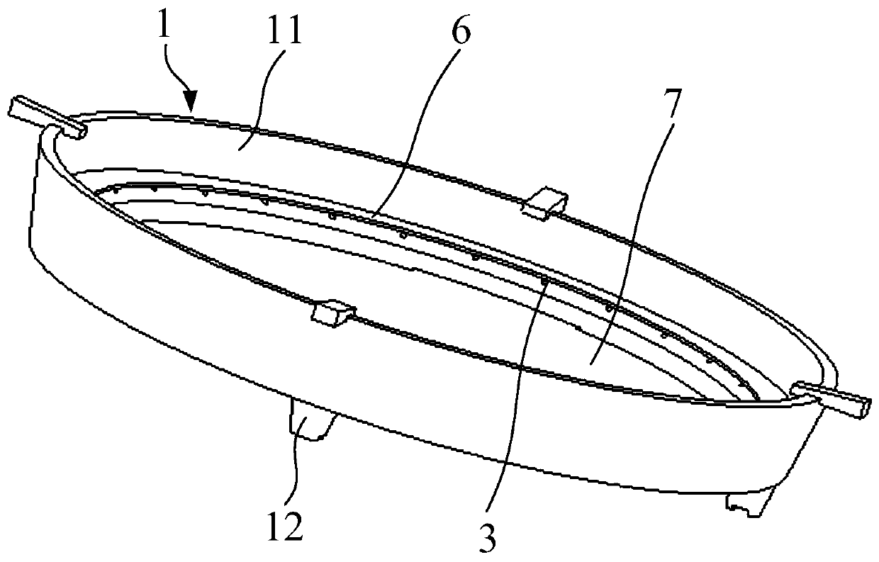
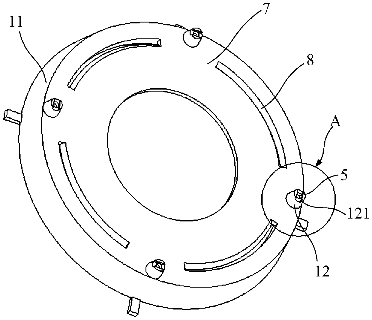
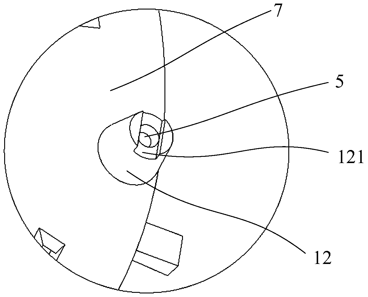
[0059] Such as Figure 1-4 As shown, the present invention provides an energy collecting plate with combustion function. The energy collecting plate 1 has an energy collecting ring wall 11, and the inside of the energy collecting ring wall 11 is provided with an annular mixing cavity 2 along the energy collecting ring. The inner side wall of the wall 11 is provided with a plurality of fire holes 3 in the circumferential direction, and the circumferential direction of the annular gas mixing chamber 2 is provided with a plurality of gas outlet channels 4 which correspond to the plurality of fire holes 3 and communicate with each other, and the annular gas mixing chamber 2 A number of ejection channels 5 communicating with the annular mixing chamber 2 are provided at the lower end.
[0060] In the energy collecting plate 1 with combustion function, the gas mixing chamber is arranged inside the wall 11 of the energy collecting ring, which has a preheating effect for the mixed gas of gas and air in the mixing stage before combustion, so as to ensure the stability and sufficient combustion of gas It can improve the combustion efficiency of gas. At the same time, the concentrating disk 1 is used in conjunction with a traditional lower air inlet burner. When installed in the burner, it is equivalent to adding another circle of fire on the basis of the original burner, which brings about an increase in combustion load. Larger, the greater the load, the greater the firepower, which can break through the maximum load of the existing household burners. Without increasing the diameter of the burner, the heating range is further enlarged, which effectively improves the heating efficiency of the gas cooker.
[0061] The bottom of the energy collecting plate 1 is provided with a plurality of legs 12, and the ejection channel 5 is provided in at least one leg 12. By arranging the ejection channel 5 in the leg 12 to form an integrated structure, it is not necessary to add a new ejection tube, and the structure is simple. In this embodiment, four legs 12 are provided at the bottom of the energy collecting plate 1, and each leg 12 has an ejection channel 5. In order to facilitate the opening of the ejection channel 5 inside the leg 12 and maintain the stability of the energy collecting plate 1 during use, the leg 12 is made into an inverted truncated cone structure, and the four legs 12 are along the bottom circumference of the energy collecting ring wall 11 The directions are evenly spaced.
[0062] The ejection channel 5 includes a shrinking cavity 51, a mixing cavity 52, and a diffusion cavity 53 arranged in sequence. The diffusing cavity 53 is arranged at the upper end of the leg 12 and communicates with the annular mixing cavity 2, and the shrinking cavity 51 is arranged at the bottom of the leg 12. The shrinking cavity 51 narrows the gas inlet channel to increase the gas flow rate, and the gas flow rate becomes larger, and the pressure near the gas will be lower than the external pressure. Under the action of the pressure difference, the outside air enters the lead through the shrinking cavity 51 The mixing chamber 52 of the injection channel 5 is mixed with gas. After entering the diffusion chamber 53, the flow rate of the mixed gas becomes slower, and the pressure near the mixed gas will be higher than the external pressure, which facilitates the rapid diffusion of the mixed gas into the annular mixing chamber 2 Inside.
[0063] In order to facilitate the entry of outside air into the ejection channel 5, a groove 121 is provided at the bottom of the leg 12. At least one side of the groove 121 penetrates the leg 12 and communicates with the contraction cavity 51, so that the outside air enters the ejection channel through the groove 121 Within 5. Wherein, the groove 121 penetrates the bottom of the leg 12 and communicates with the contraction cavity 51.
[0064] A shielding eave 6 is provided on the inner side wall of the energy collecting ring wall 11 and above the fire hole 3. The shielding eaves 6 extends outward from the inner side wall of the energy-collecting ring wall 11, and the downward orthographic projection of the shielding eaves 6 covers the fire hole 3.
[0065] The shielding eaves 6 can prevent the soup and other objects in the pot above the energy collecting plate 1 from overflowing and blocking the fire hole 3. The downward orthographic projection of the shielding eaves 6 to cover the fire hole 3 can avoid that the extended length of the shielding eaves 6 is insufficient to completely block the overflowing soup and other objects.
[0066] The bottom of the energy collecting plate 1 is provided with a bottom plate 7, and a number of through holes 8 are provided on the bottom plate 7. The through hole 8 can allow outside air to enter the energy-collecting ring wall 11 from the through hole 8, which is beneficial to the full combustion of gas.
[0067] In this embodiment, the through hole 8 is formed by the inner side wall of the energy collecting ring wall 11 extending downward and penetrating the bottom plate 7. The structure of the through hole 8 is arc-shaped, and the outer side of the arc-shaped through hole 8 and the inner side wall of the energy collecting ring wall 11 are on the same arc surface. As a result, the through hole 8 can also be used as a liquid discharge port, which can quickly discharge the overflowing soup.
[0068] In this embodiment, the inner side wall of the energy collecting ring wall 11 has an annular inclined surface 111 obliquely downward, and the fire hole 3 is provided on the annular inclined surface 111. The fire hole 3 is arranged on the annular inclined surface 111 of the inner side wall of the energy collecting ring wall 11 so that the outlet of the fire hole 3 can be inclined upward, which is beneficial to heating the bottom of the pot.
[0069] The annular air mixing chamber 2 includes a first side wall 21 connected to the ejection channel 5 and a second side wall 22 connected to the air outlet channel 4. The first side wall 21 is arranged horizontally, and the second side wall 22 is arranged diagonally downward. The third side wall 23 opposite to the second side wall 22 is parallel to the outer side wall of the energy collecting ring wall 11. With the above-mentioned structure, on the one hand, the volume of the annular gas mixing chamber 2 can be increased, so that more gas can be contained in the annular gas mixing chamber 2 to avoid heating interruption due to insufficient gas, and on the other hand, the annular gas mixing chamber 2 can be increased. The distance from the fire hole 3 increases the length of the gas outlet channel 4, so that the mixed gas keeps the gas output stable when it is sprayed from the fire hole 3. In this embodiment, the gas outlet channel 4 is arranged obliquely upward, which is beneficial to the discharge of the mixed gas.
[0070] In this embodiment, in order to make the fire emitted from the fire hole 3 uniformly heat the circumference of the bottom of the pot, a plurality of fire holes 3 are evenly spaced and distributed on the same horizontal plane along the circumferential direction of the inner wall of the energy-collecting ring wall 11 on.
[0071] The invention also discloses a gas stove, which comprises the above-mentioned energy collecting plate with combustion function.
[0072] Although the specific embodiments of the present invention have been described above, those skilled in the art should understand that this is only an example, and the protection scope of the present invention is defined by the appended claims. Those skilled in the art can make various changes or modifications to these implementations without departing from the principle and essence of the present invention, but these changes and modifications all fall within the protection scope of the present invention.

PUM

no PUM

Description & Claims & Application Information

We can also present the details of the Description, Claims and Application information to help users get a comprehensive understanding of the technical details of the patent, such as background art, summary of invention, brief description of drawings, description of embodiments, and other original content. On the other hand, users can also determine the specific scope of protection of the technology through the list of claims; as well as understand the changes in the life cycle of the technology with the presentation of the patent timeline. Login to view more.

Similar technology patents

Spray nozzle and gas turbine with same

ActiveCN104566471AImprove fire stabilityImprove combustion efficiencyContinuous combustion chamberPartially premixed combustionPower equipment
Owner:CHINA UNITED GAS TURBINE TECH CO LTD

Gas roller way kiln

Owner:青岛铸英特陶科技有限公司

Classification and recommendation of technical efficacy words

Why Eureka
Try Eureka