
Light quantum detection system, calculation method thereof and light quantum multi-phase bidirectional flowmeter employing system

A detection system and photon technology, which is applied in the direction of detecting fluid flow by measuring pressure difference, volume/mass flow generated by mechanical effects, and measuring devices, etc. It can solve the inconvenience of collimator setting, the lack of improvement in detector energy resolution, and maintenance Inconvenience and other problems, to achieve the effect of increasing or decreasing the forbidden band width, eliminating the polarization effect, and improving chemical stability

Pending Publication Date: 2019-12-20
WUXI SEA PIONEERS TECH CO LTD
View PDF2 Cites 2 Cited by
  • Summary
  • Abstract
  • Description
  • Claims
  • Application Information

AI Technical Summary

Problems solved by technology

[0012] However, the setting of the collimator is inconvenient after all. It needs to be disassembled and assembled with the detector. It is inconvenient to maintain, and the energy resolution of the detector itself has not been improved.

Method used


Image

  • Light quantum detection system, calculation method thereof and light quantum multi-phase bidirectional flowmeter employing system
  • Light quantum detection system, calculation method thereof and light quantum multi-phase bidirectional flowmeter employing system
  • Light quantum detection system, calculation method thereof and light quantum multi-phase bidirectional flowmeter employing system

Examples


Embodiment 1

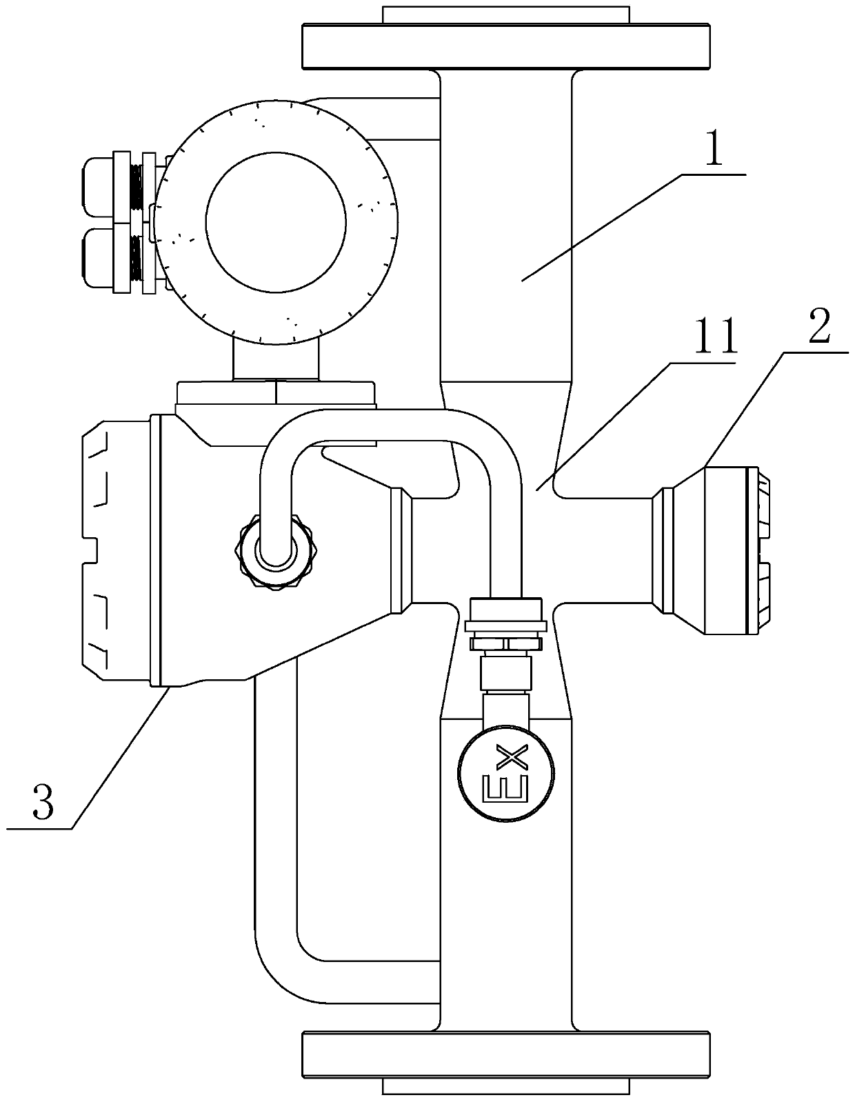
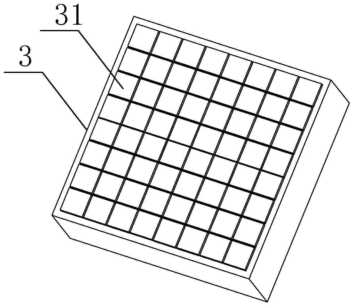
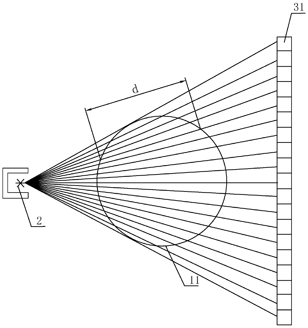
[0060] see Figure 1-2 , a light quantum detection system, including emitter 2 and detection module 3 arranged on both sides of the throttling element 1, the emitter 2 is a light quantum source, used to emit light quantum; the throttling element 1 is used for fluid to pass through, and the emitter 2 and the detection module 3 are located on both sides of the throat section 11 of the throttling element 1; the detection module 3 is a detector array, including a plurality of detection units 31 arranged in a matrix, and each detection unit 31 is used to receive the The light quanta after passing through the throttling element 1; the detection unit 31 is a CZT semiconductor detector.

[0061] The basic principle of throttling element 1 is: a throttling element 1 such as Venturi, orifice plate or nozzle is set in a circular tube filled with fluid, and the part with the smallest diameter is called throat section 11. When the fluid flows through the throttling Component 1, there will...

Embodiment 2

[0075] This embodiment is a calculation method for an optical quantum detection system, comprising the following steps:

[0076] a) Use the following formula to calculate the phase fraction α of the gas and liquid phases in a certain direction of the fluid gas 、α liquid :

[0077] N X =N o e -d·ρ·ν (1)

[0078] In formula (1), N 0 It is the number of light quanta emitted by a specific energy of the light quantum source in a specific direction, and these light quanta have not passed through the measured medium, that is, empty tube counting; N X is the number of light quanta received by the corresponding detection unit through the measured medium, that is, the real-time measurement value; d is the length of the path of the light quantum in the medium, which is a known quantity; ρ is the density of the measured medium; ν is the measured medium Linear mass absorption coefficient for light quanta;

[0079] in

[0080] ρ·v=α gas ·ρ gas ·ν gas +α liquid ·ρ liquid · v ...

Embodiment 3

[0093] see Figure 4 , the present embodiment is a photon quantum multiphase bidirectional flowmeter, including a bidirectional symmetrical throttling element 1, photon source 2 and detector 3, and the photon source 2 and detector 3 are respectively located at the throat section 11 of the throttling element 1 The two sides of the throat section 11 are provided with multi-parameter sensors 4 .


PUM


Abstract

The invention relates to a light quantum detection system, a calculation method thereof and a light quantum multi-phase bidirectional flowmeter employing the system. The light quantum detection systemcomprises an emitter and a detection module, wherein the emitter and the detection module are arranged at two sides of a throttling element, the emitter is a light quantum source and is used for emitting light quantum, the throttling element is used for a fluid to pass through, the emitter and the detection module are arranged at two sides of a throat segment of the throttling element, the detection module is a detector array and comprises a plurality of detection units arranged in a matrix form, each detection unit is used for receiving light quantum penetrating through the throttling element, and the detection units are CZT detectors. The light quantum sub-source is used as the emitter, light quantum particle with different energy is emitted, and each detection unit is used for independently measuring single photon; and with the adoption of the CZT semiconductor detector array, the light quantum detection system is small in volume and higher in energy resolution, the application ofa physical collimator can be omitted, relatively good space resolution is achieved in measurement section, so that the measurement accuracy is improved.

Description

technical field [0001] The invention relates to the field of flow detection of multiphase fluids, more specifically, it relates to an optical quantum detection system and its calculation method, and an optical quantum multiphase bidirectional flowmeter adopting the system. Background technique [0002] As China is a big consumer of oil and natural gas, how to safely store related energy has always been the top priority of the country's energy work. Storage in gas tanks poses a greater safety risk. At present, underground gas storage is generally used to store gaseous oil and natural gas in China. There are many abandoned oil wells that have been exploited in China, and abandoned oil wells can be directly used as gas storage. [0003] Liquefied oil and natural gas is purchased from abroad and then gasified first, then the gaseous oil and natural gas is injected into the gas storage, pressurized and sealed, and when needed, it is exported from the gas storage, at the entrance ...

Claims


Application Information

Patent Timeline
Patent Type & Authority Applications(China)
IPC IPC(8): G01F1/36G01F1/40G01N23/12G01T1/24
CPCG01F1/36G01F1/40G01N23/12G01T1/24G01N2223/605G01N2223/633
Inventor 陈继革高继峰季永强仝淑月刘乔平张舒漫罗超徐斌李敬阳
Owner WUXI SEA PIONEERS TECH CO LTD
Learn More