Loading device of wing hanging connector

A technology for hanging joints and loading devices, which is applied in the direction of measuring devices, testing of mechanical components, testing of machine/structural components, etc., and can solve the problem of the launch of loading devices for hanging joints, the short distance, and the inability to apply loads by actuators, etc. problems, to achieve the effect of reducing test cost and risk, convenient disassembly and assembly, and simple structure

Inactive Publication Date: 2019-12-20
BEIJING AERONAUTIC SCI & TECH RES INST OF COMAC +1
View PDF9 Cites 7 Cited by
  • Summary
  • Abstract
  • Description
  • Claims
  • Application Information

AI Technical Summary

Problems solved by technology

[0002] In the composite wing project, due to the close distance between the hanging middle joint, the hanging inner lower joint, and the hanging outer lower joint of the hanging joints, the load cannot be applied through the actuator
In order to achieve accurate and reliable loading of the aircraft wing suspension joints, it is necessary to simulate the static force and fatigue damage tolerance of the composite wing full-scale structure test suspension connection area, and to test the fatigue damage tolerance that can be changed in real time The direction of the load in the experiment, but there is no relevant loading device for the hanging joint on the market

Method used


Image

  • Loading device of wing hanging connector
  • Loading device of wing hanging connector
  • Loading device of wing hanging connector

Examples


Embodiment

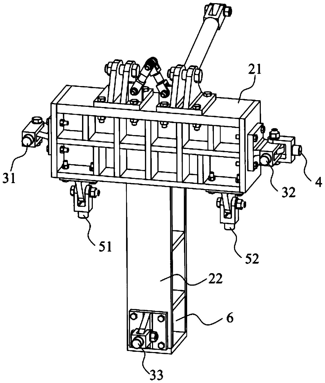
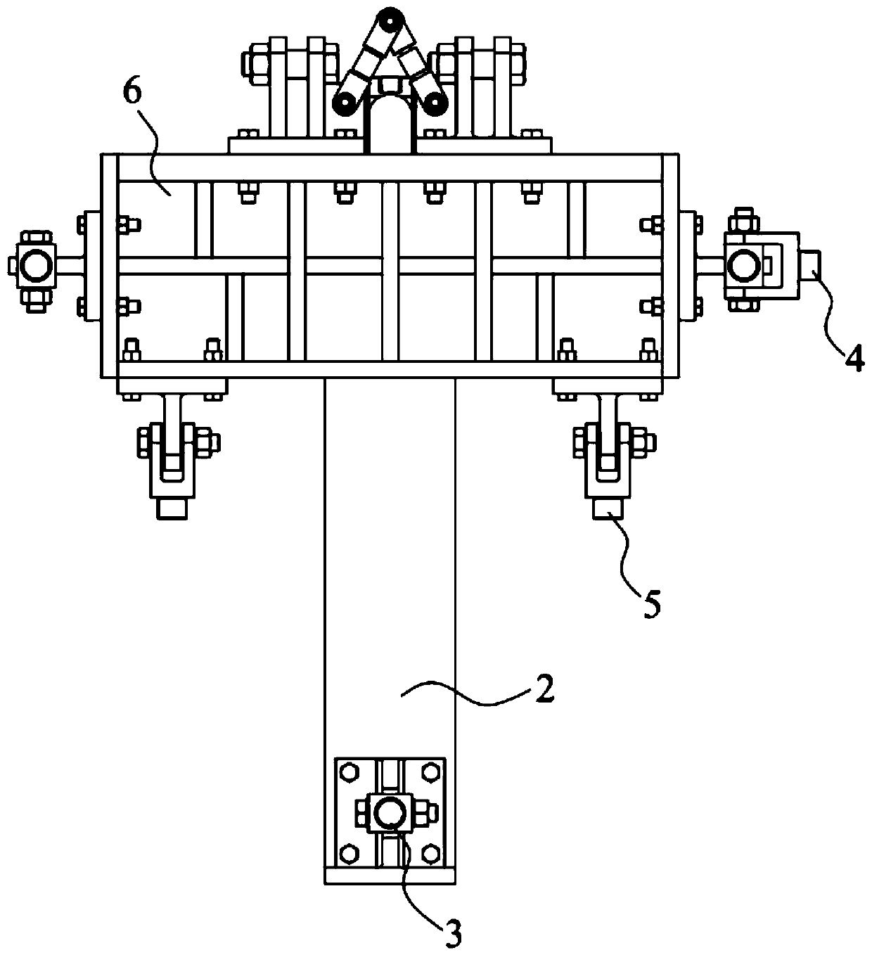
[0062] Refer below Figure 1 to Figure 4 The loading device of the wing suspension joint of a specific embodiment of the present invention is described.

[0063] Such as figure 1 As shown, the loading device of the wing suspension joint is used to ensure that the engine load is accurately transmitted to the suspension joint of the wing. The suspension joint includes an upper joint 11, an inner lower joint 12, an outer lower joint 13, and a lateral joint 14. The rear joint 15, the loading device includes a T-shaped hanging dummy 2, a first heading joint 31, a second heading joint 32, a third heading joint 33, a matching lateral joint 4, a first vertical joint 51 and a second Vertical joint 52, the hanging dummy 2 is connected with the hanging joint, the T-shaped hanging dummy 2 includes the first wall plate 21 and the second wall plate 22, the first wall plate 21 is connected with the hanging joint, the second wall The board 22 is connected to the end of the first wall board ...


PUM


Abstract

The invention discloses a loading device of a wing hanging connector. The loading device is used for guaranteeing that engine load is precisely transmitted to a hanging connector of a wing, wherein the hanging connector comprises an upper connector body, an inner side lower connector body, an outer side lower connector body, a lateral connector body and a rear connector body, the loading device comprises a hanging dummy member, a heading connector body, a matching lateral connector body and a vertical connector body, and the hanging dummy member is connected with the hanging connector body; the heading connector body is arranged on the hanging dummy member and is used for transmitting heading load to the inner side lower connector body, the outer side lower connector body and the rear connector body; the matching lateral connector body is arranged on the hanging dummy member and is used for transmitting lateral load to the lateral connector body; and the vertical connector body is arranged on the hanging dummy member and is used for transmitting vertical load to the inner side lower connector body, the outer side lower connector body, the rear connector body and the lateral connector body. The loading device can ensure that the engine load is precisely transmitted to the hanging connector of the wing, and can change the load direction in real time in a fatigue damage tolerancetest.

Description

technical field [0001] The invention relates to the field of mechanical performance testing of aircraft structures, in particular to a loading device for wing suspension joints. Background technique [0002] In the composite wing project, due to the close distance between the hanging middle joint, the hanging inner lower joint, and the hanging outer lower joint of the hanging joints, the load cannot be applied through the actuator. In order to achieve accurate and reliable loading of the aircraft wing suspension joints, it is necessary to simulate the static force and fatigue damage tolerance of the composite wing full-scale structure test suspension connection area, and to test the fatigue damage tolerance that can be changed in real time The direction of the load in the experiment, but there is no relevant loading device for the hanging joint on the market. Contents of the invention [0003] The purpose of the present invention is to propose a loading device for the win...

Claims


Application Information

Patent Timeline
Patent Type & Authority Applications(China)
IPC IPC(8): G01M13/00B64F5/60
CPCB64F5/60G01M13/00
Inventor 冯娟张楠姬杨玲杨洪琴李星张发季少华黄海龙胡震东
Owner BEIJING AERONAUTIC SCI & TECH RES INST OF COMAC
Why Eureka
Try Eureka