Wind speed online monitoring method

A technology of wind speed and air duct, which is applied in the field of primary and secondary wind monitoring in power plants, and can solve problems such as poor anti-blocking effect of pressure induction pipelines

Inactive Publication Date: 2019-12-20
GL TECH CO LTD
View PDF5 Cites 1 Cited by
  • Summary
  • Abstract
  • Description
  • Claims
  • Application Information

AI Technical Summary

Problems solved by technology

[0004] The purpose of the present invention is to provide an online wind speed monitoring method, which is used to solve the problem of poor anti-blocking effect of the pressure induction pipeline caused by the existing monitoring method

Method used


Image

  • Wind speed online monitoring method
  • Wind speed online monitoring method
  • Wind speed online monitoring method

Examples


Embodiment 1

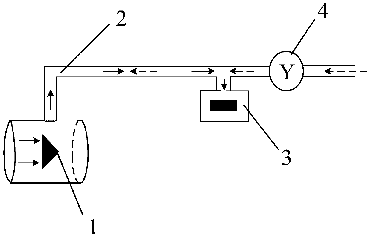
[0026] The wind speed online monitoring device applicable to this embodiment is such as figure 2 As shown, the probe air duct is included. In order to facilitate the measurement, the probe air duct is generally consistent with the extension direction of the air duct to be measured. The vortex generator 1 is set in the probe air duct, and a pressure pipe 2 is set on the probe air duct downstream of the vortex generator 1. The pressure pipe 2 is connected to the electret 3 (that is, the vortex signal detection element), and the pressure pipe The end is connected to the cleaning branch, and a pressure regulating valve 4 is provided on the cleaning branch.

[0027] During monitoring, according to the principle of Karman vortex street generation, a vortex train with a certain frequency will be generated downstream of the vortex generator 1. When the vortex is generated, the pressure near the vortex changes, and the pressure pipe 2 transmits the pressure change caused by the vortex tra...

Embodiment 2

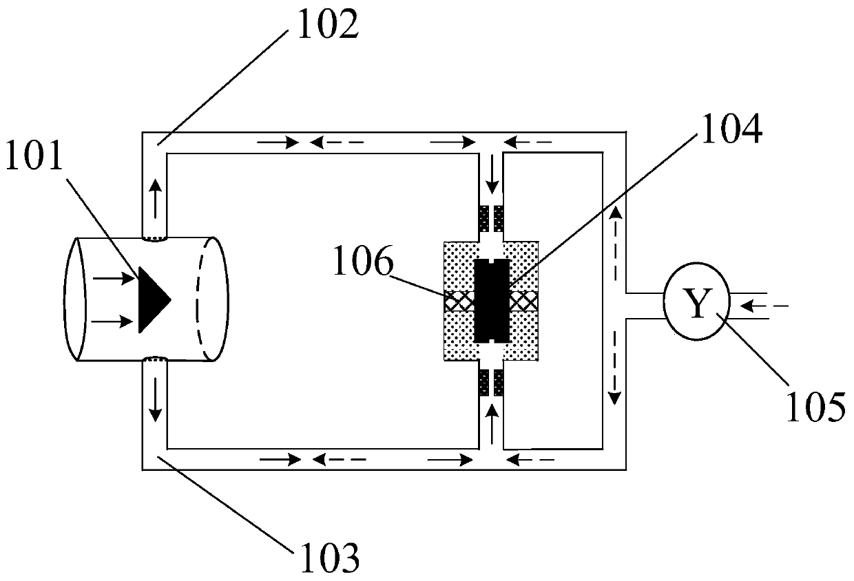
[0039] The difference between the second embodiment and the first embodiment is that the device in the second embodiment uses two pressure-inducing pipelines. When only one impulse pipeline is used, the signal waveform detected by the electret is poor. Therefore, two pressure pipes arranged symmetrically with respect to the electret are adopted. When using two pressure-inducing pipelines, the electret will not block the entire space in which it is located, so the electret is connected up and down, which can enhance the detected signal effect. The signals transmitted by the two pressure-inducing pipelines are alternating. This is because the vortex generated by the vortex generator is alternating, and vortexes are alternately generated to the two pressure-inducing pipelines.

[0040] The device applicable to the method of this embodiment is image 3 As shown, the first pressure pipe 102 and the second pressure pipe 103 are symmetrically opened on the wall of the probe air duct do...

Embodiment 3

[0043] The difference between this embodiment and the first embodiment is that in the first embodiment, the cleaning pipeline is connected to the end of the pressure-inducing pipeline; and in this embodiment, the cleaning pipeline is connected between the inlet end of the pressure-inducing pipeline and the vortex signal detection element . In other words, if the definition figure 2 The direction of the solid arrow is the downstream direction, so in this embodiment, the cleaning pipeline is upstream of the electret. In the first embodiment, the cleaning pipeline is downstream of the electret.

[0044] Such as Figure 4 As shown, a vortex generator 201 is provided in the probe air duct, and a pressure pipe 202 is opened on the probe air duct downstream of the vortex generator 201. The pressure pipe 202 has two branches, and the first branch is connected to the electret. 203. The second branch is connected to the outlet end of the pressure regulating valve 204 (that is, the clean...


PUM


Abstract

The invention relates to a wind speed online monitoring method. The method comprises the following steps: introducing a vortex signal into an impulse pipeline, wherein the vortex signal is the vibration or local pressure change produced by the vortex generated by a vortex generator; importing cleaning airflow opposite to the production of the vortex signal in the impulse pipeline, wherein a vortexsignal detection device receives the signal produced by the vortex generated by the vortex generator, computes release frequency of the vortex, and then obtains the wind flue speed. The cleaning airflow is added in the impulse pipeline while measuring the wind flue speed, the cleaning airflow is imported from a high-pressure gas source inlet, the high-pressure airflow is reduced to appropriate flow through a pressure-reducing valve. The measurement and cleaning can be synchronously performed, and the problem that the impulse pipeline is bad in anti-blocking effect due to the existing monitoring method is solved.

Description

Technical field [0001] The invention relates to the technical field of primary and secondary wind monitoring in power plants, in particular to an online wind speed monitoring method. Background technique [0002] Power plant primary and secondary air online monitoring is an important monitoring equipment for optimizing the combustion of boilers and reducing energy consumption. At present, most mainstream primary and secondary air online measurement devices use differential pressure (also called throttling) measurement methods, using fluid flow The flow measurement is achieved by the pressure difference generated by the throttling device. [0003] Because the primary and secondary air ducts contain a large amount of pulverized coal, the differential pressure measurement methods all face the problem of being easily blocked by dust. At present, there are two main ways to solve the dust clogging: 1) Intermittent cleaning method, that is, no cleaning is performed during normal measurem...

Claims


Application Information

Patent Timeline
Patent Type & Authority Applications(China)
IPC IPC(8): G01P5/01G01F1/32G01F15/12
CPCG01F1/32G01F15/12G01P5/01
Inventor 赵彤宇李波刘东旭黎智姜林赵帅军
Owner GL TECH CO LTD
Why Eureka
Try Eureka