Method and device for estimating temperature of mechanical shell of electric power system and vehicle

A technology of electric power assist and shell temperature, applied in the direction of brake safety system, electric steering mechanism, brake transmission device, etc., can solve the problems of damage to the electric power assist system, different performance of the electric power assist system, inconsistent performance, etc. Longevity, optimized safety performance, and high accuracy

Active Publication Date: 2019-12-20
上海拿森汽车电子有限公司
View PDF15 Cites 0 Cited by
  • Summary
  • Abstract
  • Description
  • Claims
  • Application Information

AI Technical Summary

Problems solved by technology

Moreover, in the prior art, the temperature of the working environment of the electric power assist system is obtained and controlled according to the resistance value of the thermistor (Negative Temperature Coefficient, NTC) on the controller (Electronic Control Unit, ECU), so as to control the temperature of the electric power assist system at this temperature Working under different temperature conditions, among them, the performance of the electric power assist system is different under different temperature environments
However, there is a problem that the temperature of the actual working environment of the electric power assist system is quite different from the temperature obtained by the resistance value of the thermistor. As a result, the performance requirements of the controller to control the performance of the electric power assist system may be different from those of the electric power assist system. The performance of the actual ambient temperature needs to be inconsistent, and long-term mismatching operations may cause damage to the electric power assist system

Method used


Image

  • Method and device for estimating temperature of mechanical shell of electric power system and vehicle
  • Method and device for estimating temperature of mechanical shell of electric power system and vehicle
  • Method and device for estimating temperature of mechanical shell of electric power system and vehicle

Examples


Embodiment Construction

[0055] The present invention will be further described in detail below in conjunction with the accompanying drawings and embodiments. It should be understood that the specific embodiments described here are only used to explain the present invention, but not to limit the present invention. In addition, it should be noted that, for the convenience of description, only some structures related to the present invention are shown in the drawings but not all structures.

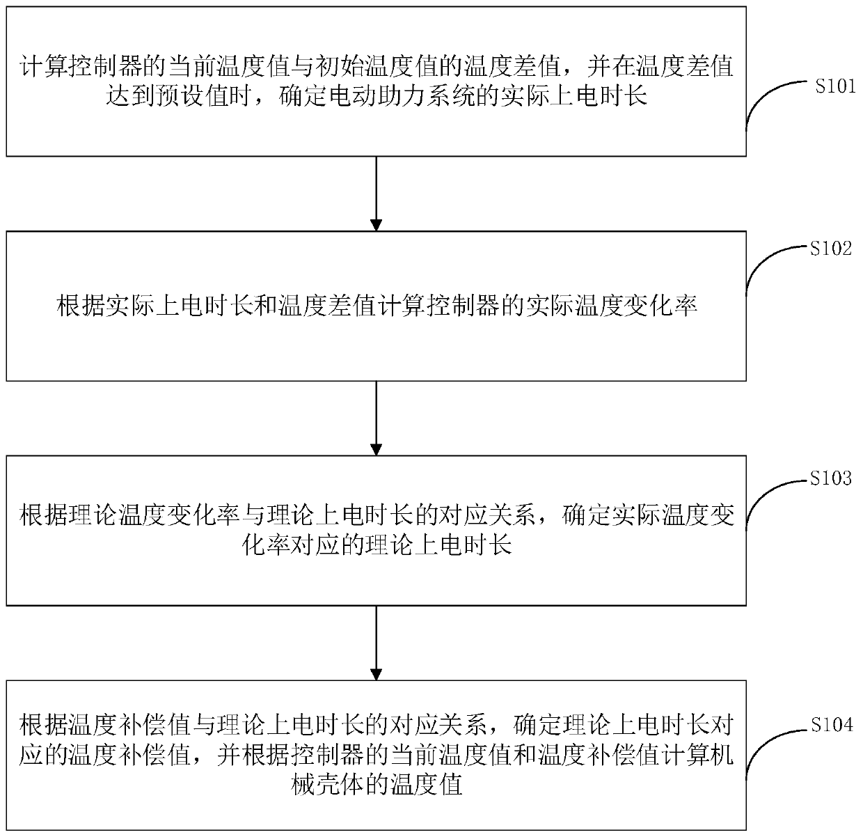
[0056] figure 1 It is a flowchart of a method for estimating the temperature of a mechanical casing of an electric power assist system according to an embodiment of the present invention. Such as figure 1 As shown, the method for estimating the temperature of the mechanical case of the electric power assist system includes:

[0057] Wherein, the electric power assist system includes a controller and a mechanical transmission system, and the mechanical transmission system includes a mechanical housing and a trans...


PUM


Abstract

The invention discloses a method and device for estimating the temperature of a mechanical shell of an electric power system and a vehicle, and the method comprises the steps: calculating a temperature difference value between a current temperature value and an initial temperature value of a controller, and determining the actual power-on duration of the electric power assisting system when the temperature difference value reaches a preset value; calculating the actual temperature change rate of the controller according to the actual power-on duration and the temperature difference value; according to the corresponding relation between the theoretical temperature change rate and the theoretical power-on duration, determining the theoretical power-on duration corresponding to the actual temperature change rate; obtaining a temperature compensation value according to a corresponding relation between the temperature compensation value and a theoretical power-on duration; and determining atemperature compensation value corresponding to the theoretical power-on duration, and calculating the temperature value of the mechanical shell according to the current temperature value and the temperature compensation value of the controller, so that the controller accurately controls the electric power-assisted system, and the controller controls a transmission device in the mechanical shellto work at the actual temperature of the mechanical shell.

Description

technical field [0001] Embodiments of the present invention relate to the technical field of automobiles, in particular to a method and device for estimating the temperature of a mechanical casing of an electric power assist system, and a vehicle. Background technique [0002] Electric power braking system or electric power steering system (Electric Power Steering, EPS) has many advantages such as simple structure, good power assist performance and energy saving compared with traditional vacuum power steering system and hydraulic power steering system. Moreover, in the prior art, the temperature of the working environment of the electric power assist system is obtained and controlled according to the resistance value of the thermistor (Negative Temperature Coefficient, NTC) on the controller (Electronic Control Unit, ECU), so as to control the temperature of the electric power assist system at this temperature Working under different temperature conditions, the performance o...

Claims


Application Information

Patent Timeline
Patent Type & Authority Applications(China)
IPC IPC(8): G06F17/50B62D5/04B60T13/74B60T17/22
CPCB62D5/04B60T13/74B60T17/22
Inventor 张万里陶喆刘倩朱心放田佰辉曹京陈进吴顺波
Owner 上海拿森汽车电子有限公司
Why Eureka
Try Eureka