Wireless automation systems and processes for wells

a technology of automation system and well, applied in the direction of program control, total factory control, instruments, etc., can solve the problems of easy off-set cost of hardwire cable installation of say thirty feet or less, hazardous ditching and trenching operations around wellhead facilities, and no economical reason to develop conventionally, so as to achieve significant enhancement of capture data integrity and functional reliability of automated well control and production optimization, and expand the input/output capability of the mrtu

Inactive Publication Date: 2007-10-18
WIXXI TECH
View PDF26 Cites 15 Cited by
  • Summary
  • Abstract
  • Description
  • Claims
  • Application Information

AI Technical Summary

Benefits of technology

[0014] It is thus seen that in the present invention the long and costly cable or hardwire wire, along with the costly trenching to put it in place that traditionally connects field end devices are replaced with a field wireless LAN data radio and the SRTU directly attached to multiple end-devices at multiple wells and/or multiple associated well facilities. This not only solves the installation cost problems associated with the topology and remoteness of the wellheads and end-devices installed at various parts of the wells production facility, it also adds or distributes the intelligence and the data of the systems to the discrete MRTUs and host device so that captured data integrity and functional reliability of automated well control and production optimization are significantly enhanced. More importantly, the present invention wirelessly expands the input/output (I/O) capability of the MRTU significantly beyond its on-board I/O counts available from a single well automation system.
[0015] Taking advantage of the teaching of the present invention that a MRTU can be used to wirelessly link SRTUs attached to end-devices associated with two or more...

Problems solved by technology

In addition, on occasion surface restrictions for wells drilled in farming or agricultural areas may require that separation/dehydration facilities as well as the tank batteries be located hundreds or even thousands of feet away from a wellhead.
It is noted that conventional RTUs referred to above are designed to automate only one well or one associated well facility as there is no economical reason to develop conventional RTU software to handle multiple wells or multiple associated well facilities because the cost of installing underground wiring to connect multiple wells and/or associated wel...

Method used


Image

  • Wireless automation systems and processes for wells
  • Wireless automation systems and processes for wells
  • Wireless automation systems and processes for wells

Examples


Embodiment Construction

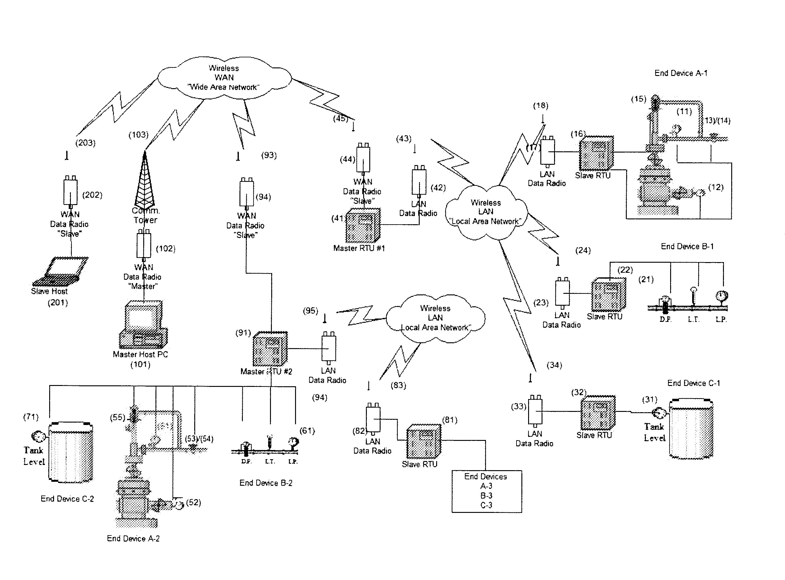
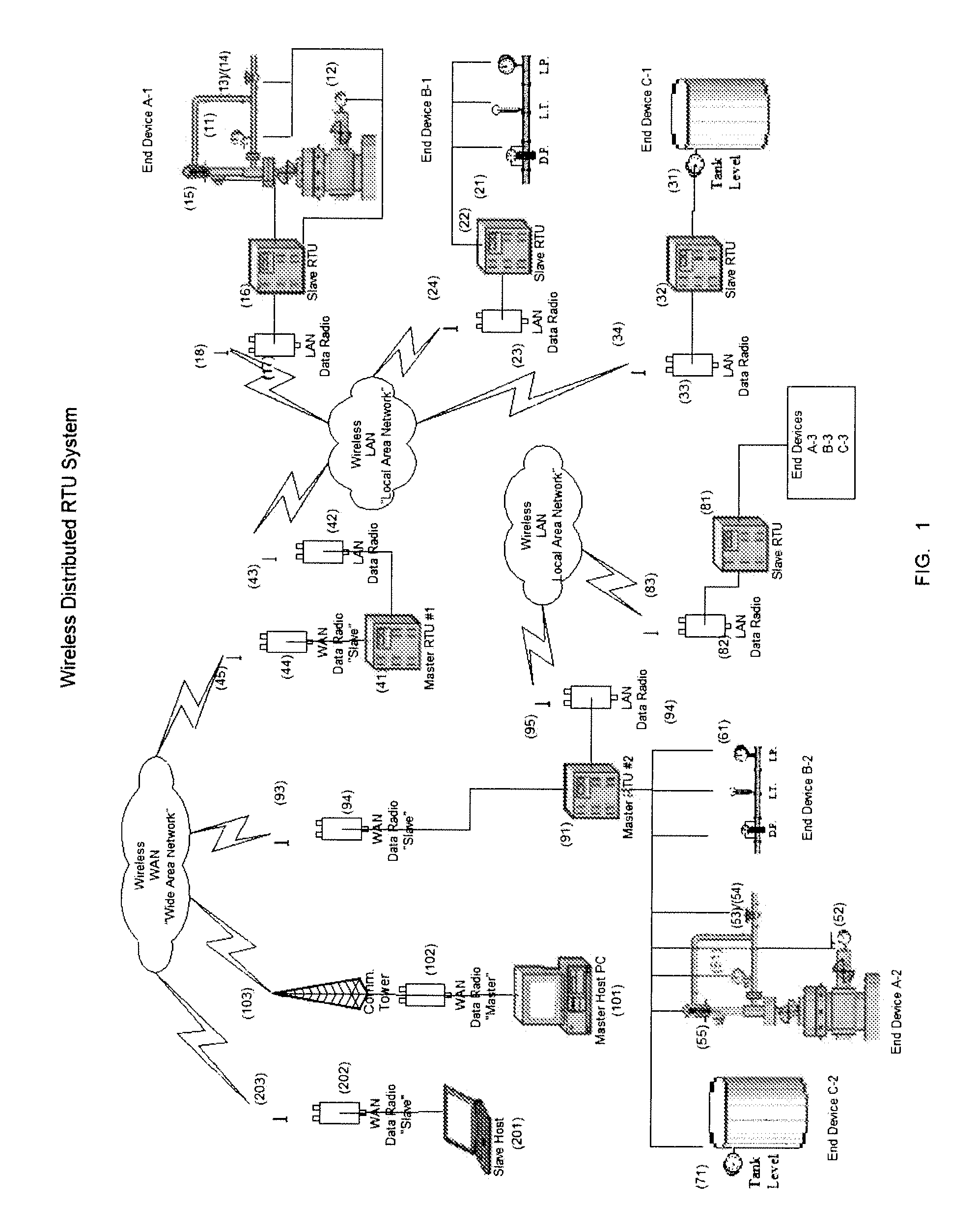
[0027] Referring to FIG. 1, a group of related end devices are shown on the right side illustrating a representative physical layout of various groups of end-devices that are commonly installed at gas or oil wellhead. These include, for example wellhead system End Device A-1, meter-run End-Device B-1, and Tank Battery system End-Device C-1. Note, as explained below in view of the teaching of the present invention, the physical proximity of the three related groups of end devices is not critical.

[0028] Well head system End Device A includes state-of the-art measuring and controlling devices such as tubing pressure transducer (11), casing pressure transducer (12), control valve (13), valve position switch (14), and plunger arrival switch (15). These are all hardwire connected in the vicinity of the wellhead to slave remote telemetry unit SRTU (16). SRTU (16) is in turn hardwire connected to radio (17) including antenna (18).

[0029] Referring again to FIG. 1, meter-run End-Device B-1,...


PUM


Abstract

This system connects groups of end-devices at two or more automated oil or gas production wellheads or groups of end-devices at two or more associated wellhead facilities so that such associated end devices may be wirelessly monitored and measured during wellhead production, and then wirelessly controlled by one or more master remote terminal/telemetry unit MRTU. Each MRTU is in turn in communication with and controlled by a host computer system. Such measurement and control of the end devices is accomplished through slave remote terminal/telemetry units SRTUs which are connected to and capable of communications with associated end-devices. Each SRTU is in turn connected to one or more local area network LAN communication system, each of which LAN is in turn connected, by hard wire or wirelessly, to a wide area network WAN transmitter. Each WAN is in wireless communication with a host computer.

Description

RELATED APPLICATIONS [0001] The present application claims the benefit under title 35 United States Code, Section ii 9(e) of U.S. provisional application No. 60 / 773,161 filed Mar. 21, 2006 entitled “Multiple well wireless automation system”; and is a continuation in part of Ocondi, M. U.S. patent application Ser. No. 10 / 536,676, filed May 27, 2005, based on PCT / US2003 / 034812 application filed Oct. 30, 2003.BACKGROUND OF THE INVENTION [0002] 1. Field of the Invention [0003] The present invention relates to a system in which one or more master remote terminal / telemetry unit (MRTU) is wirelessly connected to a central host system, for example a computing system, using wireless multi-cast networking communication to create a wide area network (WAN). The wireless multi-cast networking communication system allows an operator to monitor and control two or more automated wells and / or associated well facilities from virtually any location. [0004] 2. Background of the Related Art [0005] State...

Claims


Application Information

Patent Timeline
IPC IPC(8): G08C19/00
CPCG05B19/4185G05B2219/31151G05B2219/31448G05B2219/31162G05B2219/31229G05B2219/31158Y02P90/02
Inventor COMPTON, LARRY J.NOVAC, LUCIANOCONDI, CHAMOCONDI, MARK
Owner WIXXI TECH
Why Eureka
Try Eureka