

Ultra-wideband dielectric rod antenna for 18-40GHz frequency band
A dielectric rod, ultra-wideband technology, applied in the direction of the connection of the antenna grounding switch structure, the structural form of the radiating element, etc., can solve the problem of pattern splitting at high frequencies, the operating frequency band of the dielectric rod antenna is narrow, and the 18-40GHz frequency band cannot be fully covered. , to achieve the effect of widening the working bandwidth and avoiding the splitting of the pattern
- Summary
- Abstract
- Description
- Claims
- Application Information
AI Technical Summary
Problems solved by technology
Method used
Image

Examples
specific Embodiment approach 1
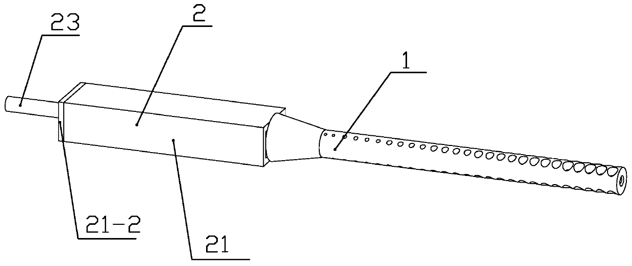
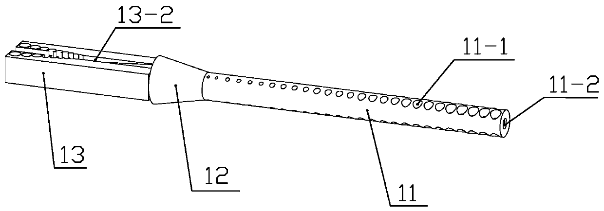
[0043] Specific implementation mode one: combine Figure 1-14 Describe this embodiment, an ultra-wideband dielectric rod antenna for the 18-40GHz frequency band, which includes a dielectric rod structure 1 and a feed structure 2, and the dielectric rod structure 1 includes a cylindrical section 11, a circular frustum section, and 12 and a transition block 13, the feed structure 2 includes a ridge waveguide 21, an impedance transformation ladder 22 and a coaxial line 23,
[0044] The outer conductor 23-1 of the coaxial line 23 is fixed to the upper ridge 21-3 of the ridge waveguide 21 through the metal plate 21-2, and the inner conductor 23-2 of the coaxial line 23 is connected to the lower ridge 21 of the ridge waveguide 21 through the impedance transformation step 22. Ridge 21-4 is fixedly connected,
[0045] The upper ridge 21-3 of the ridge waveguide 21 includes a first ridge segment 21-31 and a second ridge segment 21-32, the first ridge segment 21-31 has a rectangular bl...
specific Embodiment approach 2
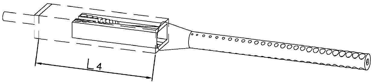
[0068] Specific implementation mode two: combination Figure 1-14 To illustrate this embodiment, the outer dimension A of the width of the shell of the ridge waveguide 21 is 9.4 mm, the inner dimension a of the shell is 7.4 mm, the outer dimension B of the height of the shell is 6.2 mm, and the inner dimension b of the height of the shell is 4.2 mm. The body axial length L4 is 32 mm.
[0069] The length L of the lower ridge 21-4 6 is 23.1mm, the width of the lower ridge 21-4 is 1.83mm, and the ridge curve adopts the form of an exponential function:
[0070] y=e kx -1, x∈[0,23.1]
[0071] Where x represents the distance of the ridge curve along the axial direction of the ridge waveguide 21, y represents the vertical distance between the ridge curve and the inner surface of the ridge waveguide 21, k is used to adjust the shape of the curve, and k is 0.037.
[0072] The dielectric rod structure 1 is made of polytetrafluoroethylene material with a relative permittivity of 2.2....
PUM
| Property | Measurement | Unit |
|---|---|---|
| External dimensions | aaaaa | aaaaa |
| Axial length | aaaaa | aaaaa |
| Length | aaaaa | aaaaa |
Abstract
Description
Claims
Application Information