Helically grooved folded waveguide

A folded waveguide and helical groove technology, which is applied in the directions of waveguides, waveguide-type devices, traveling wave tubes, etc., can solve the problems of beam-wave interaction efficiency, overall performance degradation of devices, and relative bandwidth limitation of folded waveguide traveling wave tubes, etc. Working bandwidth, the effect of increasing power

Inactive Publication Date: 2016-12-07
成都赛纳为特科技有限公司
View PDF7 Cites 0 Cited by
  • Summary
  • Abstract
  • Description
  • Claims
  • Application Information

AI Technical Summary

Problems solved by technology

This imposes a severe limitation on the relative bandwidth of the folded waveguide TWT
Another problem with ordinary folded waveguide traveling wave tubes is the efficiency of the beam-wave interaction due to the single e-book
At home and abroad, there are plans to adopt 2 to 3 el

Method used


Image

  • Helically grooved folded waveguide
  • Helically grooved folded waveguide
  • Helically grooved folded waveguide

Examples


Embodiment 1

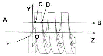
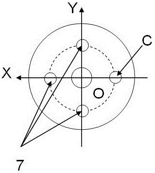
[0028] Such as figure 1 and 2 shown.

[0029] The helical groove folded waveguide includes three shortest waveguide periods 2 and input and output waveguides 1 that are successively connected and repeated along the Z-axis direction.

[0030] The intersection of a straight line AB parallel to the Z axis and any one of the shortest waveguide periods is a continuous line segment CD.

[0031] Four linear electronic channels 7 are provided. The straight beam path 7 is parallel to the Z axis. The straight electron beam channel 7 coincides with the straight line AB. The line segment CD passes through the maximum amplitude point of the electric field strength of the electromagnetic wave in the shortest waveguide period. That is to say, the straight electron channel 7 passes through the position of the maximum electric field intensity in the spiral groove folded waveguide.

[0032] The two end faces of the shortest waveguide period are single-ridge rectangular waveguides; the bro...

Embodiment 2

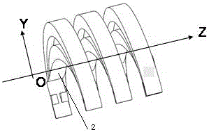
[0036] Such as image 3 shown.

[0037] Compared with Embodiment 1, the only difference is that: the two ends of the shortest waveguide period are double-ridge rectangular waveguides; the broadside of any end surface of any of the shortest waveguide periods is parallel to the Y-axis direction, and the The double ridges of the double ridge rectangular waveguide are respectively located on the two broad sides of the waveguide.

Embodiment 3

[0039] Such as Figure 4-10 shown. Compared with implementation example 1, the difference is only in:

[0040] Both ends of the shortest waveguide period are parallel to the YZ plane. The shape of both ends of the shortest waveguide period is rectangular; the broad sides of any shortest waveguide period are parallel to the Y-axis direction.

[0041]The 6 shortest waveguide periods of the spiral groove folded waveguide are arranged on a cylindrical inner conductor 9 ; the outer surfaces of the multiple shortest waveguide periods coincide with the outer surface of the cylindrical inner conductor 9 .

[0042] The spiral groove folded waveguide also includes two outer conductors 9a; the inner surfaces of the outer conductors 9a coincide with the outer surfaces of the cylindrical inner conductor 9; all the outer conductors 9a seal the outer surface of the inner conductor.

[0043] A total of 8 linear electron beams are provided.

[0044] We have given several implementation exa...


PUM


Abstract

The invention discloses a helically grooved folded waveguide. The helically grooved folded waveguide comprises at least two shortest waveguide period structures connected in sequence along a Z axis and input and output waveguides. The waveguides are rectangular waveguides, single-ridged rectangular waveguides or double-ridged rectangular waveguides. The helically grooved folded waveguide is formed by bending a waveguide section with a certain cross section along a helical line around the Z axis. When the helically grooved folded waveguide is applied to a linear electromagnetic wave vacuum device such as a traveling wave tube and the like, compared with a traditional folded waveguide, the helically grooved folded waveguide has the advantages that a 180-degree phase difference due to a U-shaped bent waveguide when electron beams pass through a traditional slow-wave structure is overcome, and the working bandwidth of an electromagnetic wave source can be better extended. Meanwhile, the number of linear electron beam channels can be increased to two or more, and the beam-wave interaction efficiency can be remarkably improved. The helically grooved folded waveguide also can be used for compact delay lines realizing various waveguides, single-ridged waveguides or double-ridged waveguides.

Description

technical field [0001] The invention relates to an electromagnetic wave transmission line. Specifically, it relates to a compact helical groove folded waveguide for signal delay or slow wave structure for electromagnetic wave source. Background technique [0002] The first important application of folded transmission lines was as a signal delay line, used for signal delay in systems such as radar. A second important application of folded transmission lines is as a slow wave structure in traveling wave tube amplifiers. At this time, the electron beam propagates along a certain straight electron channel, while the electromagnetic wave propagates along the bent transmission line. Although the phase velocity of the electromagnetic wave propagating in the folded transmission line is very fast, which can be close to the speed of light, or even greater than the speed of light, in the linear electron channel, the phase velocity of the electromagnetic wave felt by the electron beam...

Claims


Application Information

Patent Timeline
IPC IPC(8): H01P3/10H01P9/00H01J23/24H01J25/34
CPCH01P3/10H01J23/24H01J25/34H01P9/006
Inventor 王清源
Owner 成都赛纳为特科技有限公司
Why Eureka
Try Eureka