Connecting structure of main beam and supporting legs of bridge girder erection machine

A technology for connecting structures and bridge erecting machines, which is applied in the erection/assembly of bridges, bridges, bridge construction, etc., can solve the problems of difficult to adjust the longitudinal height of the main girder of bridge erection, difficult to adjust the curve section of bridge erection, etc., to save time and structure. Simple, easy-to-use effects

Active Publication Date: 2019-12-24
HEFEI ZHENGHAO MECHANICAL TECH
View PDF7 Cites 2 Cited by
  • Summary
  • Abstract
  • Description
  • Claims
  • Application Information

AI Technical Summary

Problems solved by technology

[0006] (1) How to make the main girder of the bridge can be adjusted in the longitudinal direction of the column through the setting of the gantry, so as to solve the problem that it is difficult to adjust the longitudinal height of the main girder of the bridge in the prior art;
[0007] (2) How to use the servo motor to drive the driving roller and the driven roller to rotate, so that the pull rope drives the slider to slide in the limit groove, the slider drives the bottom plate to move, and the turntable on the bottom plate adjusts the angle according to actual needs to solve the problem In the prior art, it is difficult to directly adjust the bridging curve section without dismantling the erecting device

Method used


Image

  • Connecting structure of main beam and supporting legs of bridge girder erection machine
  • Connecting structure of main beam and supporting legs of bridge girder erection machine
  • Connecting structure of main beam and supporting legs of bridge girder erection machine

Examples


Embodiment Construction

[0028] The technical solutions of the present invention will be clearly and completely described below in conjunction with embodiments. Obviously, the described embodiments are only a part of the embodiments of the present invention, rather than all the embodiments. Based on the embodiments of the present invention, all other embodiments obtained by those of ordinary skill in the art without creative work shall fall within the protection scope of the present invention.

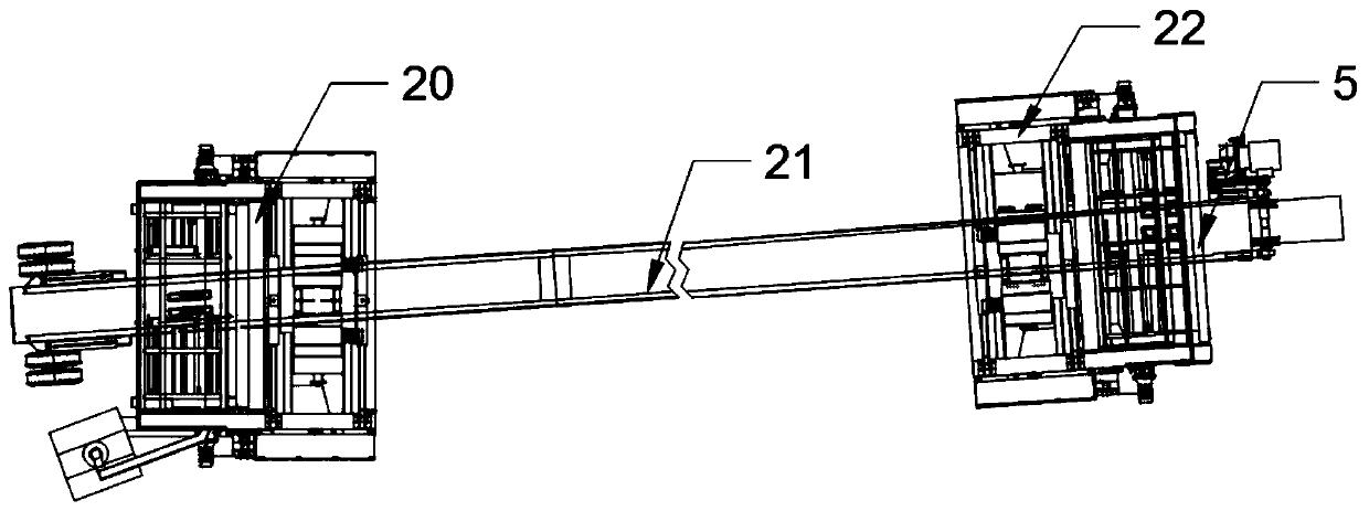
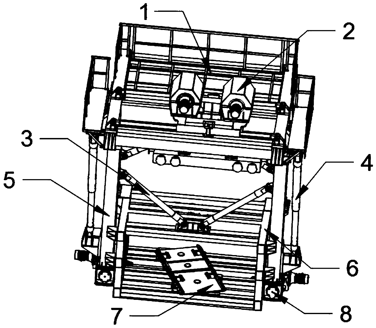
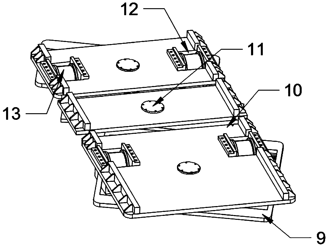
[0029] See Figure 1-5 As shown, a connecting structure of the main beam and outrigger of a bridge erecting machine includes a load-bearing platform 1, a lifting mechanism 2, a tie rod 3, a connecting rod 4, a column 5, a gantry 6, a rotating mechanism 7, a power pulley mechanism 8, a support The leg 20, the main beam mechanism 21 and the bridge pier 22. Both ends of the main beam mechanism 21 are provided with legs 20 and piers 22, and the legs 20 are fixedly connected to the bridge pier 22. One end of the main ...


PUM


Abstract

The invention discloses a connecting structure of a main beam and supporting legs of a bridge girder erection machine. The connecting structure comprises a bearing platform, a lifting mechanism, a pull rod, connecting rods, stand columns, a gantry, a rotating mechanism, a power pulley mechanism, the supporting legs, a main beam mechanism and bridge piers, wherein both ends of the main beam mechanism are provided with the supporting legs and the bridge piers, and the supporting legs are fixedly connected with the bridge piers; one end of the main beam mechanism is symmetrically provided with the stand columns, one end of the main beam mechanism is provided with a bearing platform, and the bottom of the bearing platform is fixedly connected with the top end of the two symmetrically arrangedstand columns; and the top of the bearing platform is fixedly provided with the lifting mechanism, and the lower part of the bearing platform is provided with the gantry. According to the connecting structure, a servo motor drives a driving roller and a driven roller to rotate, so that a pull rope drives a sliding block to slide in a limiting slot, and the sliding block drives a bottom plate to move; and a rotary table on the bottom plate adjusts the angle according to the actual needs, so that when the bridge girder erection machine is in curved section and skew bridge, the proper angle is needed to be rotated and the bridge is directly erected and parts do not need to be dismantled.

Description

Technical field [0001] The invention relates to a connecting structure, in particular to a connecting structure of a main beam and a support leg of a bridge erecting machine, and belongs to the technical field of bridge erecting machine application. Background technique [0002] The bridge erecting machine is the equipment that puts the prefabricated beams on the prefabricated bridge piers. The bridge erecting machine belongs to the category of cranes, because its main function is to lift the beams, then transport them to the location and then put them down. But it is very different from the crane in the general sense. The requirements are harsh, and there is a traveling on the beam, or it is called longitudinal shift. Bridge erecting machines are divided into several types such as erecting highway bridges, conventional railway bridges, and passenger dedicated railway bridges. [0003] The existing patent publication number is a new type of bridge erecting machine CN201058969, w...

Claims


Application Information

Patent Timeline
Patent Type & Authority Applications(China)
IPC IPC(8): E01D21/00
CPCE01D21/00
Inventor 郑之松
Owner HEFEI ZHENGHAO MECHANICAL TECH
Why Eureka
Try Eureka