Design method of centrifugal compressor and diffuser structure

A design method and compressor technology, applied in mechanical equipment, machines/engines, instruments, etc., can solve the problems of enhanced gas viscosity, large diffuser size, large structure size, etc., to improve the compression capacity and high pressure capacity. and diffusing capacity, the effect of improving the gas flow state

Active Publication Date: 2019-12-24
CHANGCHUN UNIV OF SCI & TECH
View PDF5 Cites 3 Cited by
  • Summary
  • Abstract
  • Description
  • Claims
  • Application Information

AI Technical Summary

Problems solved by technology

[0003] At present, the existing centrifugal compressor has a large structural size, a long axial dimension, and a large weight
However, the existing diffuser structure is segmented vane diffuser, the size of the diffuser is larger, the gas viscosity in the diffuser channel is strengthened, and the friction loss is larger; or the wedge-shaped vane channel diffuser, in At the turning point from axial to radial, blending and turning from radial to axial on the meridian surface, boundary layer and secondary flow appear at the same time, with large losses

Method used


Image

  • Design method of centrifugal compressor and diffuser structure
  • Design method of centrifugal compressor and diffuser structure
  • Design method of centrifugal compressor and diffuser structure

Examples


Embodiment Construction

[0033] Embodiments of the present invention will be described below with reference to the accompanying drawings. Those skilled in the art would recognize that the described embodiments can be modified in various ways or combinations thereof without departing from the spirit and scope of the invention. Accordingly, the drawings and description are illustrative in nature and not intended to limit the scope of the claims. Also, in this specification, the drawings are not drawn to scale, and like reference numerals denote like parts.

[0034] Acronyms and key term definitions

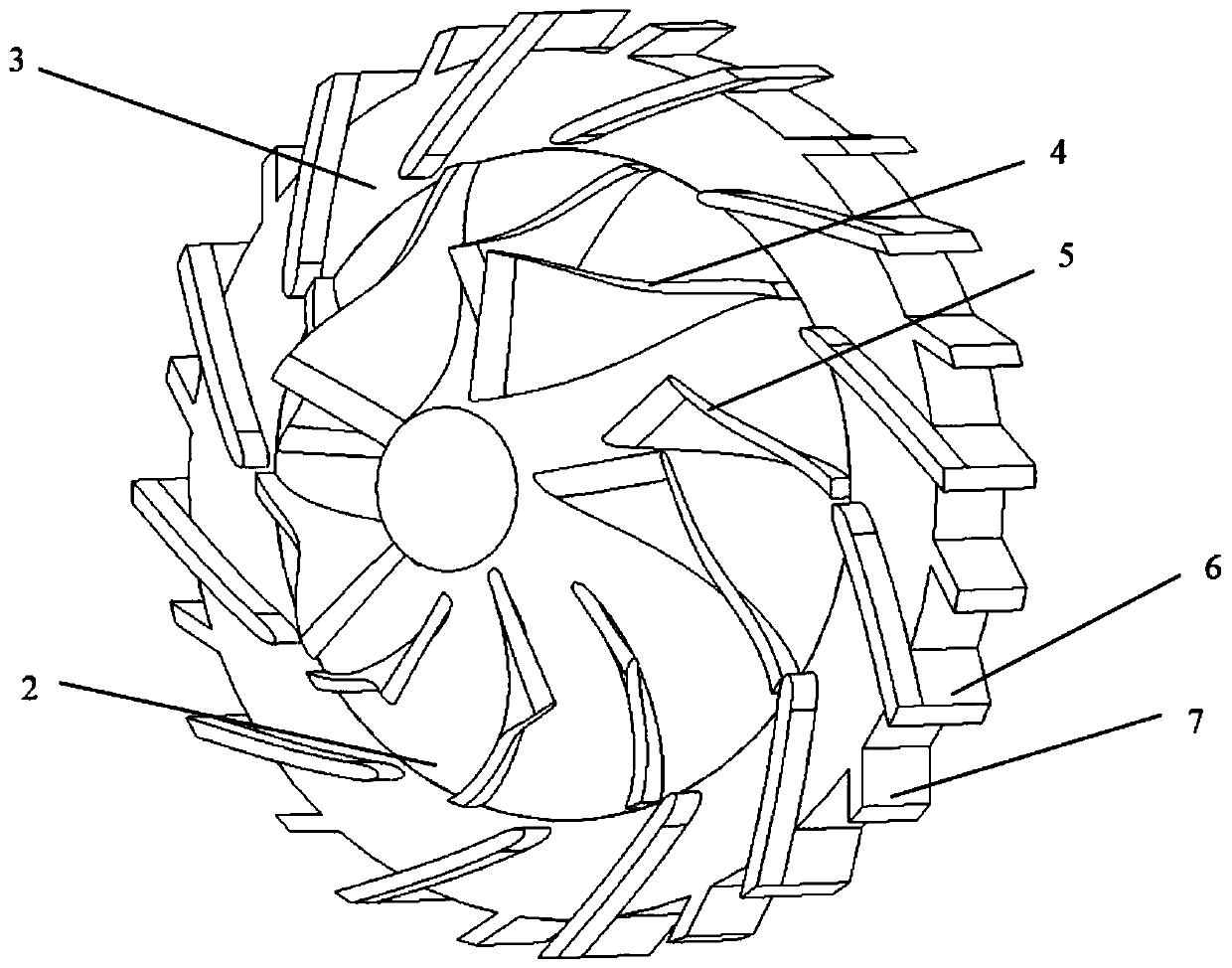
[0035] Centrifugal impeller: The high-speed rotating blades are used to convert the energy between the flowing medium and the shaft power, and the centrifugal force generated by the rotation of the impeller increases the pressure of the medium.

[0036] Diffuser: Decelerate and diffuse the high-speed airflow at the outlet of the impeller, so that the kinetic energy obtained by the gas in the impeller can ...


PUM


Abstract

The invention discloses a design method of a centrifugal compressor and a diffuser structure. The centrifugal compressor comprises a shell, an impeller and a diffuser, wherein the impeller comprises ahub and impeller blades, the diffuser comprises diffuser blades; and the design method comprises the following steps that curve segments of the shell and the hub of the impeller adopt Bezier curve design, and curve segments of the impeller blades adopt 3D free curve design; and curve segments of the diffuser blades adopt spiral curve design. Through the parametric design method, a gas inlet angleat a gas inlet hole and a gas outlet angle at a gas outlet hole are optimized, a gas flow state is improved, the uniformity of an outlet gas flow is improved, the gas flow loss is reduced, and high gas compressing capability and diffusion capability are obtained under the condition of small size.

Description

technical field [0001] The invention relates to the field of turbojet engine equipment, in particular to a design method of a centrifugal compressor and a diffuser structure thereof. Background technique [0002] Micro turbojet engine (Micro Turbine Engine, MTE) has the advantages of small size, light weight, high energy density, etc., and is widely used in the energy field. The centrifugal compressor is the core component of the micro-turbojet engine, and its design level directly affects the overall performance of the micro-turbojet engine. Compared with the axial flow compressor, the centrifugal compressor has the characteristics of light weight, small volume and high single-stage pressure ratio, so it is widely used in micro turbojet engines. [0003] At present, the existing centrifugal compressor has a large structural size, a long axial dimension, and a large weight. However, the existing diffuser structure is segmented vane diffuser, the size of the diffuser is lar...

Claims


Application Information

Patent Timeline
Patent Type & Authority Applications(China)
IPC IPC(8): F04D29/44F04D29/28F04D29/30F04D29/66G06F17/50
CPCF04D29/284F04D29/30F04D29/444F04D29/667
Inventor 徐玉东张心明吕琼莹熊恒穆国振
Owner CHANGCHUN UNIV OF SCI & TECH
Why Eureka
Try Eureka