Flange assembling device for hollow composite insulator

A technology for composite insulators and assembly devices, applied in the direction of insulators, electrical components, circuits, etc., can solve the problems of troublesome assembly process, high cost, and inability to mix and use directly, and achieve the effect of simple structure and convenient assembly process

Active Publication Date: 2019-12-27
JIANGSU XIANGYUAN ELECTRIC EQUIP
View PDF6 Cites 3 Cited by
  • Summary
  • Abstract
  • Description
  • Claims
  • Application Information

AI Technical Summary

Problems solved by technology

[0004] Although the above-mentioned assembly device also realizes the assembly of the insulator end flange, it has certain limitations in the process of use, that is, the above-mentioned assembly device, due to its assembly and needs to use It is realized by the cooperation of hydraulic presses, slide rails, etc. Therefore, considering the stroke of the hydraulic press and the processing requirements of insulators of different lengths, most of them are suitable for the assembly of insulators with relatively long lengths. At present, in factory processing, A certain amount of insulators with relatively short lengths will also be produced. When assembling these insulators, they cannot be mixed and used directly. It may be necessary to customize another assembly device with a short stroke, and the cost is relatively high. At the same time, the insulator is positioned according to the size, and then the flange is clamped and positioned by the clamp, and then the hydraulic presses on both sides work at the same time to realize the assembly of the flange. The entire assembly process is also relatively troublesome, and it is not suitable for short-length insulators.

Method used


Image

  • Flange assembling device for hollow composite insulator
  • Flange assembling device for hollow composite insulator
  • Flange assembling device for hollow composite insulator

Examples


Embodiment Construction

[0026] The following examples can enable those skilled in the art to understand the present invention more comprehensively, but the present invention is not limited to the scope of the described examples.

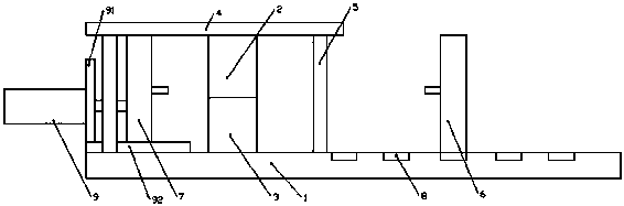
[0027] Such as Figure 1-Figure 7 A hollow composite insulator flange assembly device shown, including

[0028] An assembly base 1, the assembly base 1 is a cuboid structure.

[0029] An insulator positioning assembly installed on the assembly base 1, the insulator positioning assembly includes an insulator positioning upper mold 2, an insulator positioning lower mold 3, the insulator positioning lower mold 3 is directly fixed on the assembly base 1, the insulator positioning lower mold 3 and the assembly base 1 The insulator positioning upper mold 2 is installed on the assembly base 1 through the upper template 4, and the insulator positioning upper mold 2 is fixed on the bottom of the upper template 4 through bolts. The upper template 4 is in a rectangular shape, and the...


PUM


Abstract

The invention relates to a flange assembling device for a hollow composite insulator. The flange assembling device comprises an assembling base; an insulator positioning assembly arranged on the assembling base, wherein the insulator positioning assembly comprises an insulator positioning upper die and an insulator positioning lower die, a first positioning cavity is formed in the lower end of theinsulator positioning upper die, a second positioning cavity is formed in the upper end of the insulator positioning lower die, and the first cavity and the second cavity are jointly matched to forma positioning cavity for installing an insulator; and a flange positioning assembly which comprises a pair of flange positioning plates which are respectively positioned at two sides of the insulatorpositioning assembly. The device has the advantages that the assembling base, the insulator positioning assembly and the flange positioning assembly are matched, so the flanges at the two ends of an insulator can be assembled only through one assembling oil cylinder; the structure is simple, the whole assembling process is very convenient, and the device is suitable for assembling flanges of insulators of different sizes.

Description

technical field [0001] The invention relates to the field of insulator processing, in particular to a flange assembly device for hollow composite insulators. Background technique [0002] At present, when the hollow composite insulator is prepared, the metal accessories at the end and the insulating pipe are assembled, and the method of pouring epoxy resin is mostly used. The characteristic of this method is that there is a large gap between the flange and the pipe to facilitate the filling of the ring. Oxygen resin glue, this gap has a great influence on the shape and position tolerance of the assembled product. The product after filling the epoxy resin needs to be placed in a special oven to cure. In addition, as hollow composite insulators are becoming more and more popular in the power industry The disadvantages of using the above method to prepare insulators in mass production are more and more obvious. Before the product is poured, special tooling is required to assemb...

Claims


Application Information

Patent Timeline
Patent Type & Authority Applications(China)
IPC IPC(8): H01B19/00
CPCH01B19/00
Inventor 张德进刘铁桥张斌张达武纪福俊章玉秀朱勇飞王丹丹秦锦华
Owner JIANGSU XIANGYUAN ELECTRIC EQUIP
Why Eureka
Try Eureka