
Motor structure

A technology of motor structure and positioning column, which is applied in the direction of magnetic circuit shape/style/structure, electrical components, electromechanical devices, etc., can solve the problems of cumbersome installation process, low efficiency, difficulty, etc., achieve convenient and fast installation, increase installation speed, The effect of improving waterproof performance

Pending Publication Date: 2019-12-27
苏州柯姆电器有限公司
View PDF0 Cites 1 Cited by
  • Summary
  • Abstract
  • Description
  • Claims
  • Application Information

AI Technical Summary

Problems solved by technology

[0003] The existing motor is fixed and installed by a bracket. During installation, the bracket needs to be opposed to the connection hole on the stator, and the bolts are inserted for connection. It is difficult to align multiple bolt holes at the same time, and the installation process is very cumbersome and inefficient.

Method used


Image

  • Motor structure
  • Motor structure
  • Motor structure

Examples


Embodiment Construction

[0043] The present invention will be described in further detail below in conjunction with the accompanying drawings.

[0044] In the description of the present invention, it should be noted that unless otherwise specified and limited, the terms "installation", "connection" and "connection" should be understood in a broad sense, for example, it can be a fixed connection or a detachable connection. Connected, or integrally connected; it can be mechanically connected or electrically connected; it can be directly connected or indirectly connected through an intermediary, and it can be the internal communication of two components. Those of ordinary skill in the art can understand the specific meanings of the above terms in the present invention in specific situations.

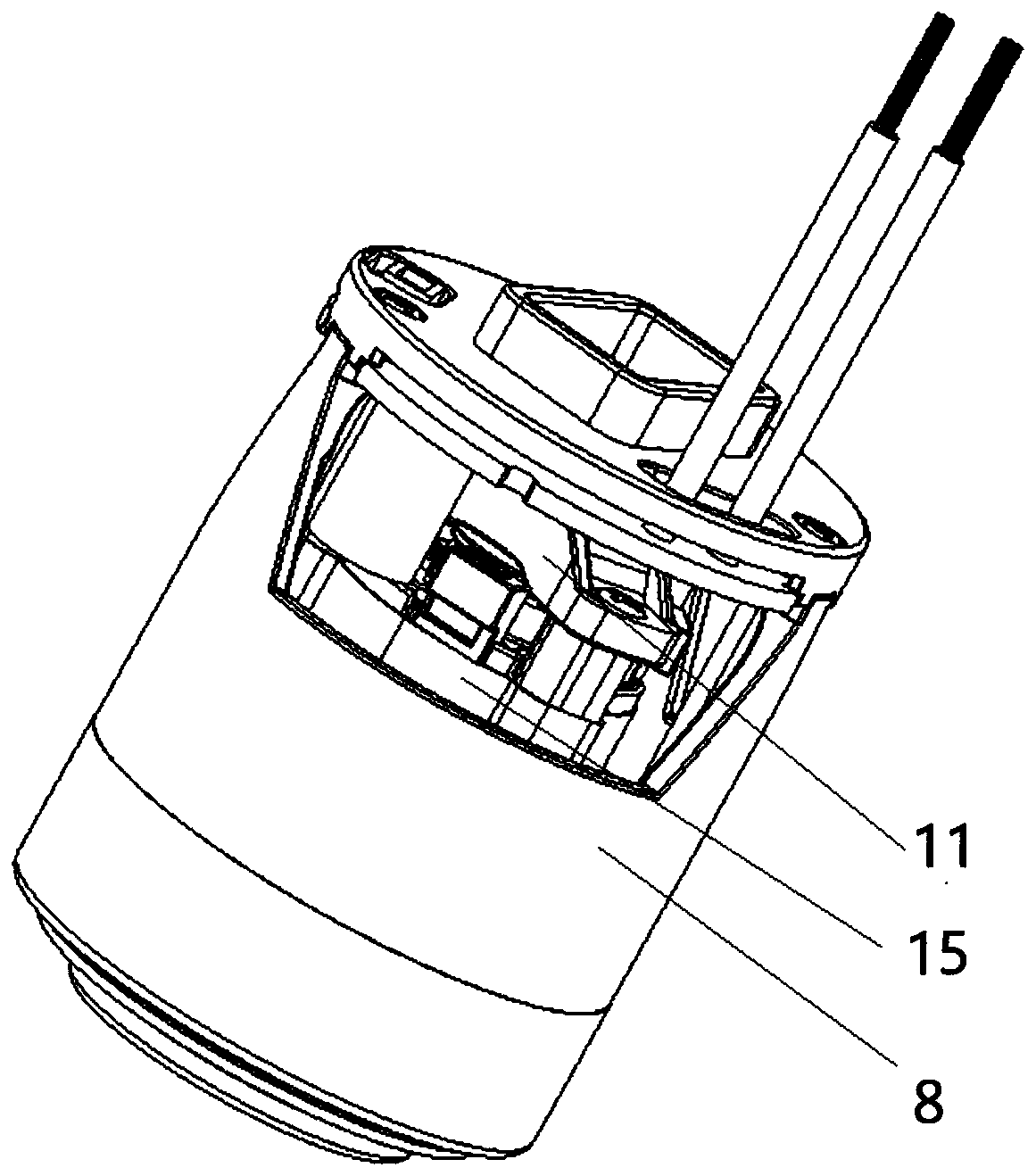
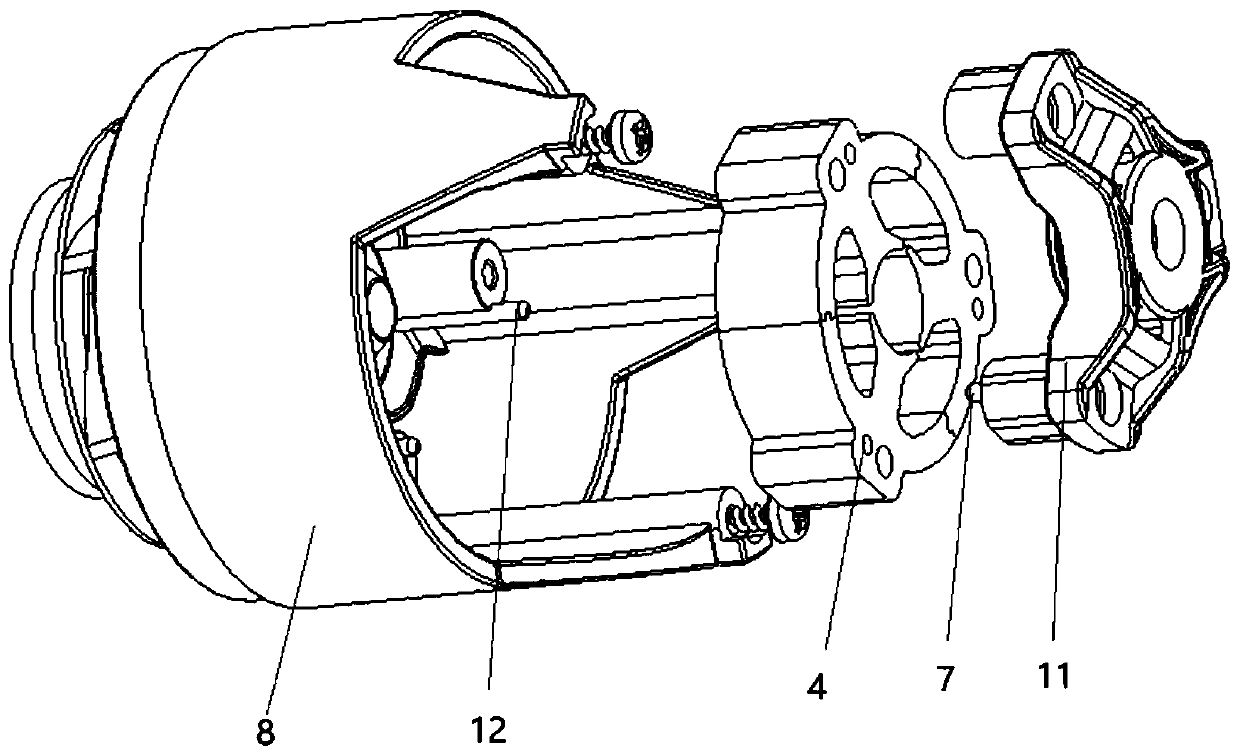
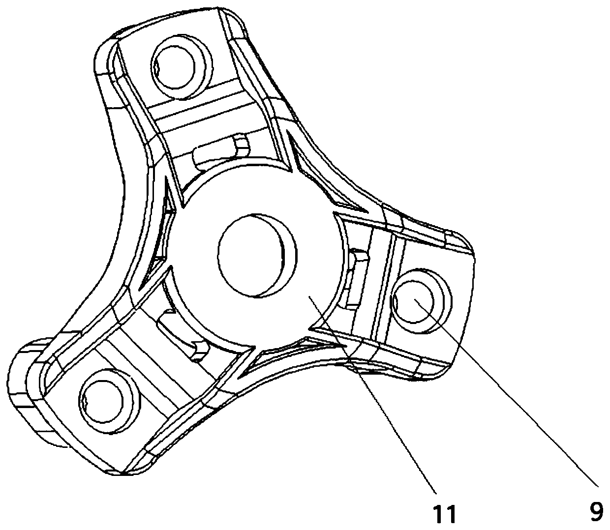
[0045] An embodiment of the present invention: as figure 1 As shown, a kind of motor structure comprises upper support 11, and described upper support 11 is provided with central hole; Lower support 8, described l...


PUM


Abstract

The invention discloses a motor structure. The motor structure comprises an upper support having a center hole for penetration of a rotor, a lower support having a center hole for penetration of the rotor, a stator, a rotor, wherein a lower portion of the stator is connected with the lower support, an upper portion of the stator is fixed through the upper support, a center hole for the rotor to penetrate is formed at the center of the stator, the rotor penetrates through the lower support, the stator and the upper support and is installed on the upper support and the lower support, and positioning devices are arranged on the lower support, the upper support and the stator. The motor structure is advantaged in that the positioning devices are arranged on the upper support, the lower supportand the stator, during installation, positioning columns are inserted into iron cores firstly, then the installation position can be accurately found, and the installation speed is greatly increased.

Description

technical field [0001] The invention relates to the field of motor manufacturing, in particular to a motor structure. Background technique [0002] The main function of the motor is to generate driving torque. As a power source for electrical appliances or various machines, the existing small automatic cleaning equipment (such as sweeping robots, vacuum cleaners, mopping machines, etc.) all need the motor to provide a power source for suction work. [0003] The existing motor is fixed and installed by a bracket. During installation, the bracket needs to be opposed to the connection hole on the stator, and bolts are inserted for connection. However, it is difficult to align multiple bolt holes at the same time. The installation process is very cumbersome and inefficient. Contents of the invention [0004] The object of the present invention is to provide a motor structure, which can quickly locate the position of the bracket and the stator during installation, and improve t...

Claims


Application Information

Patent Timeline
Patent Type & Authority Applications(China)
IPC IPC(8): H02K5/00H02K5/04H02K1/14H02K5/20H02K5/24H02K5/10H02K5/22
CPCH02K5/00H02K5/04H02K1/148H02K5/20H02K5/24H02K5/10H02K5/22
Inventor 杨贵文
Owner 苏州柯姆电器有限公司
Learn More