Electric-attraction type dispensing equipment and control method thereof

A control method and dispensing technology, which are used in liquid spraying equipment, electrostatic spraying devices, spraying devices, etc., can solve the problem of difficulty in ensuring the size, weight and offset of the dispensing fluid, difficulty in ensuring the yield, and difficulty in precise glue control. Accurate positioning and other problems, to achieve the effect of fast dispensing rate, precise glue control, and precise positioning

Inactive Publication Date: 2019-12-31
天一新能源(东莞)有限公司
View PDF6 Cites 0 Cited by
  • Summary
  • Abstract
  • Description
  • Claims
  • Application Information

AI Technical Summary

Problems solved by technology

[0003] At present, the dispensing methods of the dispensing machine mainly include contact dispensing and non-contact dispensing. The contact dispensing is mainly the syringe pressure type, so that the dispensing needle can be in contact with the surface of the product as much as possible for the dispensing operation. Contact dispensing is jet dispensing; but these two types of dispensing methods are difficult to achieve precise glue control and precise positioning, that is, it is difficult to ensure the size, weight and offset of the dispensing fluid, and the yield is difficult to guarantee. The processing efficiency of the dispensing method is low

Method used


Image

  • Electric-attraction type dispensing equipment and control method thereof
  • Electric-attraction type dispensing equipment and control method thereof
  • Electric-attraction type dispensing equipment and control method thereof

Examples


Embodiment Construction

[0024] In order to facilitate the understanding of those skilled in the art, the present invention will be further described below in conjunction with the examples, and the contents mentioned in the embodiments are not intended to limit the present invention.

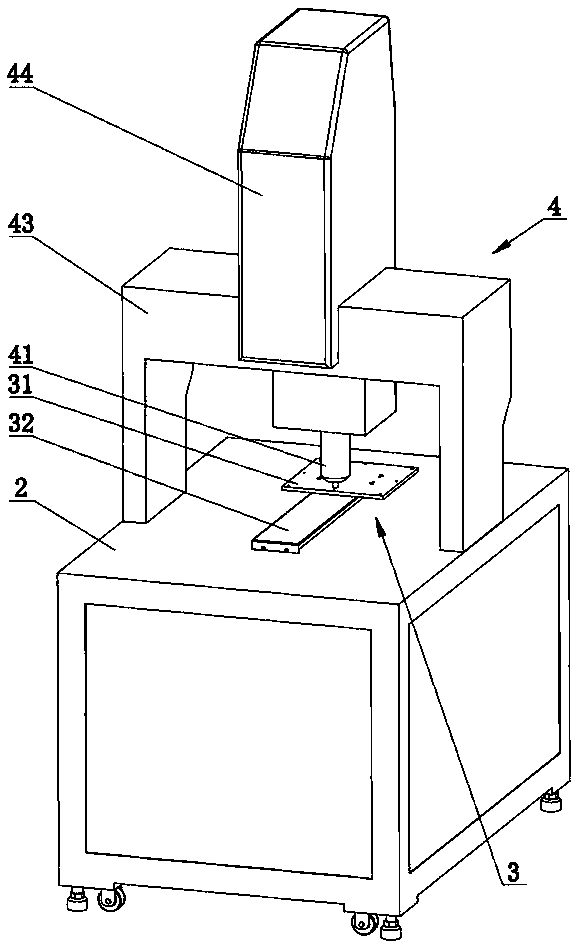
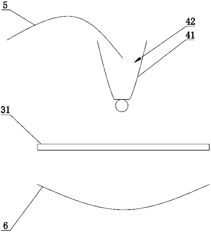
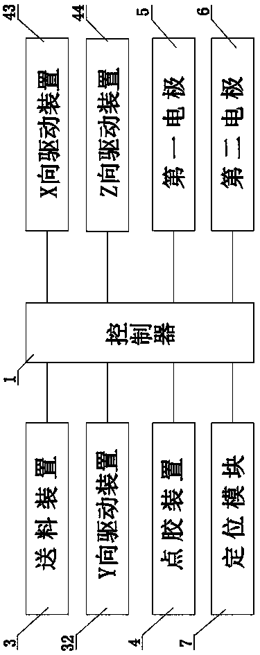
[0025] Such as Figure 1 to Figure 3 As shown, an electric suction dispensing equipment includes a controller 1, a frame 2, a feeding device 3 arranged on the frame 2, and a fluid quantitative output device 4 located above the feeding device 3. The fluid quantitative output device 4 Comprising a dispensing head 41 located on the feeding device 3 and a glue chamber 42 set inside the dispensing head 41 for accommodating fluid, the feeding device 3 and the fluid quantitative output device 4 are electrically connected to the controller 1, and Including a first electrode 5 and a second electrode 6 with opposite polarities and electrically connected to the controller 1, one end of the first electrode 5 is electrically connect...


PUM


Abstract

The invention relates to the technical field of dispensing equipment, in particular to electric-attraction type dispensing equipment and a control method thereof. The electric-attraction type dispensing equipment comprises a controller, a machine frame, a feeding device and a fluid quantitative output device, wherein the feeding device is arranged on the machine frame, and the fluid quantitative output device is arranged on the feeding device; the fluid quantitative output device comprises a dispensing head arranged on the feeding device and a glue cavity arranged inside the dispensing head, and the feeding device and the fluid quantitative output device are electrically connected with the controller; and the electric-attraction type dispensing equipment further comprises a first electrodeand a second electrode which are opposite in polarity and are electrically connected with the controller, wherein one end of the first electrode is electrically connected with the glue cavity, and the second electrode is arranged below the feeding device. According to the electric-attraction type mode, the size of a fluid glue bead can be changed and the weight of the fluid glue bead can be ensured through the controller according to the production requirements; and meanwhile according to the principle of opposite polarity attraction, it is ensured that the fluid glue bead is not deflected inthe flying process so that precise glue control and precise positioning can be achieved, and the electric-attraction type dispensing mode can reach 1000 Hz per second, so that the dispensing rate isextremely fast, and the machining efficiency is greatly improved.

Description

technical field [0001] The invention relates to the technical field of dispensing equipment, in particular to an electric suction dispensing equipment and a control method thereof. Background technique [0002] The glue dispenser is mainly used for accurate pointing, injecting, coating, and dripping of glue, paint and other liquids in the product process to the precise position of each product, and can be used to achieve dots, lines, circles or arcs. [0003] At present, the dispensing methods of the dispensing machine mainly include contact dispensing and non-contact dispensing. The contact dispensing is mainly the syringe pressure type, so that the dispensing needle can be in contact with the surface of the product as much as possible for the dispensing operation. Contact dispensing is jet dispensing; but these two types of dispensing methods are difficult to achieve precise glue control and precise positioning, that is, it is difficult to ensure the size, weight and offse...

Claims


Application Information

Patent Timeline
Patent Type & Authority Applications(China)
IPC IPC(8): B05B5/08
CPCB05B5/08B05B5/082B05B5/087
Inventor 尹东明房文平尹贺李川川
Owner 天一新能源(东莞)有限公司
Why Eureka
Try Eureka