Surface paint spraying device for tubular connection part for architectural engineering
A technology for construction engineering and connecting parts, which is applied to devices for coating liquid on surfaces, spraying devices, spray booths, etc., can solve problems such as reducing production efficiency, affecting the cleanliness of the working environment, and uneven painting of workpieces, and improving painting efficiency. , Guarantee the effect of painting quality
- Summary
- Abstract
- Description
- Claims
- Application Information
AI Technical Summary
Problems solved by technology
Method used
Image

Examples
Embodiment 1
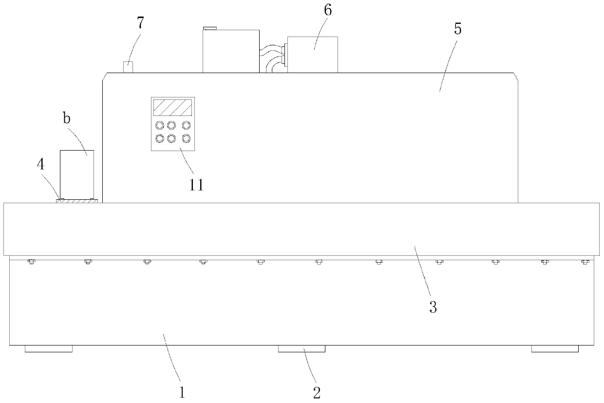
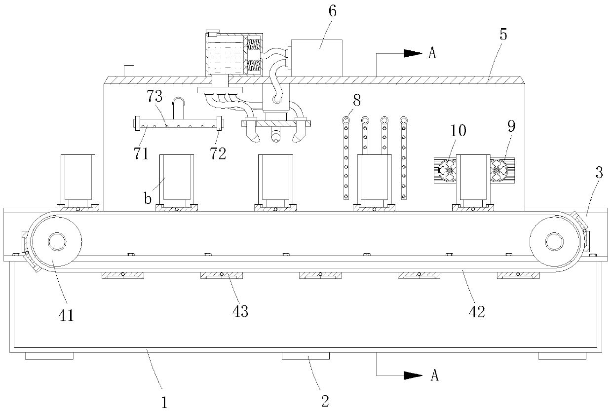
[0044]A surface painting device for tubular connectors used in construction projects, comprising a base box 1 and a plurality of support feet 2 installed at the lower end of the base box 1, and two C-shaped brackets are symmetrically installed on both sides of the upper end of the base box 1 by combining bolts and nuts. The side panels 3, and the upper ends of the two C-shaped side panels 3 are provided with a spray booth 5, and the four are combined together to form a frame for installation, which is used for the installation of the painting mechanism to ensure the overall painting of the tubular connector b. A transmission mechanism 4 is provided between the two C-shaped side panels 3 for automatic transmission of the tubular connector b, and an electrostatic dust removal mechanism is arranged in the inner cavity of the spray booth 5 along the movement direction of the transmission mechanism 4 from left to right. 7. The painting mechanism 6 and the hot air drying mechanism 8 ...
Embodiment 2
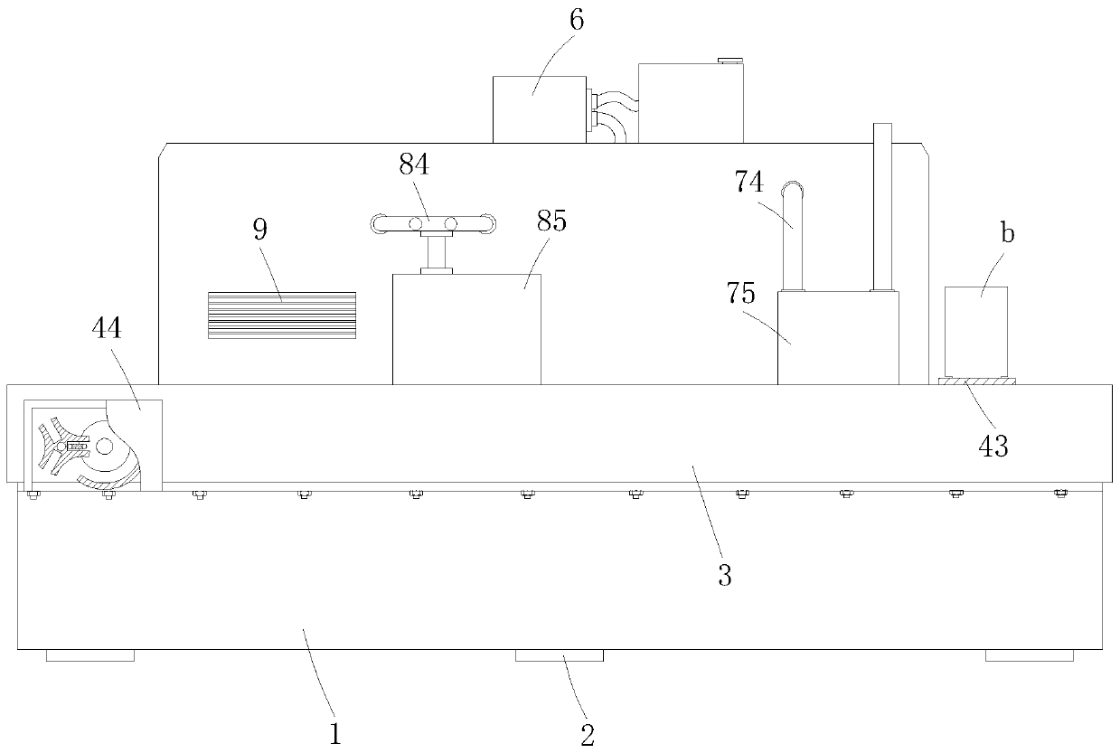
[0060] The difference between this embodiment and embodiment 1 is that, as figure 2 and 3 As shown, an exhaust grid 9 is embedded on the rear wall of the spray booth 5 close to the output end of the transmission mechanism 4, and a plurality of exhaust fans 10 are installed on the exhaust grid 9, and the exhaust fans 10 are activated to dissipate heat The waste gas and paint irritating gas generated after the fan 85 sprays out the drying are discharged through the exhaust grid 9. It can be understood that the exhaust grid 9 can be used in conjunction with the exhaust pipe to realize fast drying while ensuring the cleanliness of the processing environment. clean.
[0061] Refer to Example 1 for other undescribed structures.
PUM
 Abstract
Description
Claims
Application Information
 - R&D
- Intellectual Property
- Life Sciences
- Materials
- Tech Scout
- Unparalleled Data Quality
- Higher Quality Content
- 60% Fewer Hallucinations
Browse by: Latest US Patents, China's latest patents, Technical Efficacy Thesaurus, Application Domain, Technology Topic, Popular Technical Reports.
© 2025 PatSnap. All rights reserved.Legal|Privacy policy|Modern Slavery Act Transparency Statement|Sitemap|About US| Contact US: help@patsnap.com