Towel rack automatic welding machine

An automatic welding machine and towel rack technology, applied in welding equipment, welding equipment, auxiliary welding equipment and other directions, can solve the problems of workpiece and workpiece welding seam dislocation, low work efficiency, scrapping and other problems, and achieve high positioning dimensional accuracy and work efficiency. high effect

Inactive Publication Date: 2019-12-31
JIANGXI AVONFLOW HVAC TECH CO LTD
View PDF0 Cites 6 Cited by
  • Summary
  • Abstract
  • Description
  • Claims
  • Application Information

AI Technical Summary

Problems solved by technology

[0004] The purpose of the present invention is to provide an automatic welding machine for towel racks, to solve the problems in the above-mentioned background technology that most enterprises now use the gears for the positioning of the support rods and hanging rods when welding the towel racks, and the original technology such as backing. It leads to inaccurate positioning and large dimensional errors, which in turn causes the workpiece to be misaligned with the weld seam, causing incomplete welding, incomplete fusion, pits, undercuts and other defects, resulting in poor air tightness and liquid leakage, resulting in poor quality of the towel rack, and even Scrapped, resulting in economic losses, low work efficiency and high labor costs

Method used


Image

  • Towel rack automatic welding machine
  • Towel rack automatic welding machine
  • Towel rack automatic welding machine

Examples


Embodiment Construction

[0023] The following will clearly and completely describe the technical solutions in the embodiments of the present invention with reference to the accompanying drawings in the embodiments of the present invention. Obviously, the described embodiments are only some, not all, embodiments of the present invention. The specific embodiments described here are only used to explain the present invention, not to limit the present invention. Based on the embodiments of the present invention, all other embodiments obtained by persons of ordinary skill in the art without making creative efforts belong to the protection scope of the present invention.

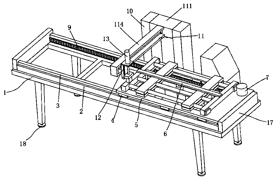
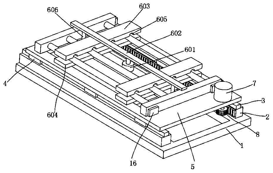
[0024] The present invention provides such Figure 1-5 The shown automatic towel rack welding machine at least includes a frame 1 , a positioning and pressing mechanism 6 and a welding head moving mechanism 11 .

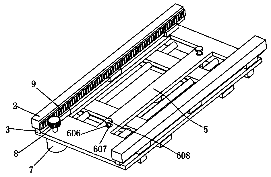
[0025] Both sides of the upper end of the frame 1 are fixed with a mounting block 2, the upper end of the mounting block 2 is...


PUM


Abstract

The invention discloses a towel rack automatic welding machine. The towel rack automatic welding machine comprises a rack. Mounting blocks are fixed to the two sides of the upper end of the rack, guide rails are fixed to the upper ends of the mounting blocks, sliding blocks slide on the guide rails, a carrying frame is fixed to the upper ends of the sliding blocks, a positioning and pressing mechanism is arranged in the middle of the carrying frame, a first servo motor is mounted on the upper side of one end of the carrying frame, the end of an output shaft of the first servo motor is in key connection with a gear, the gear is located below the carrying frame, a rack is engaged with one side of the gear, the rack is fixed to the side faces of the mounting blocks, a supporting frame is arranged in the middle of the rear side of the rack, a moving mechanism is arranged at the upper end of the supporting frame, an air cylinder mounting frame is arranged on the moving mechanism, a first air cylinder is mounted on the air cylinder mounting frame, a mounting plate is fixed to the end of a piston rod of the first air cylinder, and a welding head is mounted on the lower side of the mounting plate. Towel rack accessories are positioned and automatically pressed, the position is automatically changed, the working efficiency is high, and the machining quality is good.

Description

technical field [0001] The invention belongs to the technical field of towel rack welding machines, and in particular relates to an automatic welding machine for towel racks. Background technique [0002] The electric towel rack is a high-tech product, which is a supporting product for high-end bathrooms. It is widely used in families (bathroom space, kitchen, balcony), high-end residences, villas, hotels, guesthouses, inns, medical and elderly care institutions, and public service places (such as hairdressing and beauty salons) , sauna, foot massage, sports venues) and other places. [0003] Most of the frame of the towel rack is composed of two support rods and multiple hanging rods. The multiple hanging rods need to be welded between the two support rods at equal distances. Now most enterprises weld the towel racks with the support rods and the hanging rods. The original technology such as gear position and backing for positioning, such original technology leads to inacc...

Claims


Application Information

Patent Timeline
Patent Type & Authority Applications(China)
IPC IPC(8): B23K31/02B23K37/04
CPCB23K31/02B23K37/0443
Inventor 吴剑斌文勇张国林胡以兵
Owner JIANGXI AVONFLOW HVAC TECH CO LTD
Why Eureka
Try Eureka