
Automatic file placing and taking manipulator

A technology of manipulator and mechanical arm, applied in the field of automatic access file manipulator, can solve the problems of affecting the efficiency of management staff, unstable placement, troublesome access, etc., to reduce personnel costs and time costs, broad application prospects, and simple structure. Effect

Pending Publication Date: 2019-12-31
JIANGSU XUNJIE HARNESS TECH
View PDF0 Cites 1 Cited by
  • Summary
  • Abstract
  • Description
  • Claims
  • Application Information

AI Technical Summary

Problems solved by technology

[0002] At present, the use of intelligent filing cabinets has become very common. It is used to store files of various models, classifications, and categories. The existing intelligent filing cabinets are very troublesome to access. Generally, the access operations are performed manually, which requires a lot of manpower and resources. The equipment investment has seriously affected the efficiency of the management staff, which is very inconvenient and makes the work efficiency very low; and the file rack set on the existing manipulator will have a compartment for placing the file box corresponding to each file box. The spacing between the files is the same, so when the file box is relatively thin, the file box will be looser when placed in the compartment, and it will fall if it is not placed stably. When the file box is thicker, it cannot be put in at all. Therefore, the existing manipulator The file rack placed can only hold file boxes of the same thickness, which cannot meet the use of existing intelligent file cabinets, which is very inconvenient

Method used


Image

  • Automatic file placing and taking manipulator
  • Automatic file placing and taking manipulator
  • Automatic file placing and taking manipulator

Examples


Embodiment Construction

[0043] In order to deepen the understanding of the present invention, the present invention will be further described in detail below in conjunction with the accompanying drawings and embodiments, which are only used to explain the present invention and do not limit the scope of protection.

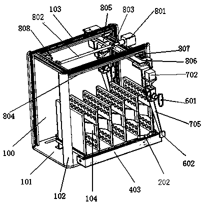
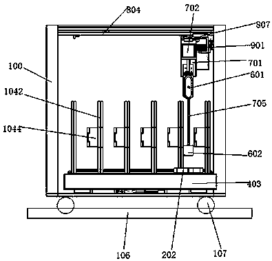
[0044] Referring to the figures, where figure 1 The schematic diagram of the two suction cup assemblies in is the state diagram of the position during the storage and retrieval process. The device actually only has one suction cup assembly and lifting assembly.

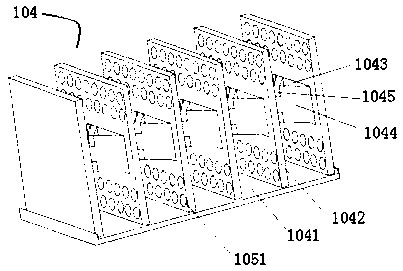
[0045] An automatic file access manipulator, including a frame 100 and a mechanical arm arranged on the frame, the frame includes a square base 101 and uprights 102 arranged on the four corners of the base 101, two adjacent uprights The tops are connected by cross bars 103, the base 101 is provided with a self-positioning file rack 104, the front of the file rack 104 is provided with an opening and closing door 200, and the botto...


PUM


Abstract

The invention provides an automatic file placing and taking manipulator. The manipulator comprises a frame and a mechanical arm arranged on the frame; the frame comprises a square base and vertical rods arranged at the four corners of the base, wherein the tops of two adjacent vertical rods are connected through a cross rod, a self-positioning file rack is arranged on the base, an opening and closing door is arranged in front of the file rack, a lifting mechanism is arranged below the file rack, and the base is further provided with a pushing mechanism and a moving mechanism for controlling the opening and closing door to move horizontally; and the mechanical arm comprises a sucker mechanism, a lifting assembly, a translation assembly and a pushing assembly, wherein the lifting assembly, the translation assembly and the pushing assembly control the sucker mechanism to move up and down, horizontally and back and forth respectively, the translation assembly is arranged above the frame, the pushing assembly is arranged on the translation assembly, the lifting assembly is arranged on the pushing assembly through a connecting piece, and the sucker mechanism comprises a sucker and a supporting plate arranged on the lifting assembly.

Description

technical field [0001] The invention relates to the technical field of file management, in particular to an automatic file access manipulator. Background technique [0002] At present, the use of intelligent filing cabinets has become very common. It is used to store files of various models, classifications, and categories. The existing intelligent filing cabinets are very troublesome to access. Generally, the access operations are performed manually, which requires a lot of manpower and resources. The equipment investment has seriously affected the efficiency of the management staff, which is very inconvenient and makes the work efficiency very low; and the file rack set on the existing manipulator will have a compartment for placing the file box corresponding to each file box. The spacing between the files is the same, so when the file box is relatively thin, the file box will be looser when placed in the compartment, and it will fall if it is not placed stably. When the f...

Claims


Application Information

Patent Timeline
Patent Type & Authority Applications(China)
IPC IPC(8): B65G1/04B65G47/90
CPCB65G1/04B65G47/901
Inventor 贡仲林贡晓燕谢骐阳张全生吴新军王永志刘芳华
Owner JIANGSU XUNJIE HARNESS TECH
Learn More