Punching, film pasting and capping machine

A technology of cap locking machine and film sticking, applied in the field of cap locking machine, can solve the problems of inaccurate processing position, weak sticking of aluminum foil paper, and insufficient locking of the lid, etc., so as to shorten the working time, reduce labor costs, and save labor and costs. Effect

Active Publication Date: 2019-12-31
广东希顿智能机器有限公司
View PDF7 Cites 3 Cited by
  • Summary
  • Abstract
  • Description
  • Claims
  • Application Information

AI Technical Summary

Problems solved by technology

[0002] The capping machine, also known as capping machine, capping machine and capping machine, is used for screwing and loosening the caps of plastic bottles and glass bottles (molded bottles or tube bottles). It is used for aluminum caps or aluminum-plastic caps crimping and sealing of antibiotic powder injection glass bottles (molded bottles or tube bottles), as well as packaging of beverage bottles. It is widely used in beverage and purified water industries. Currently, it is used in daily chemical, In the extruded tube hose and composite hose in the pharmaceutical and food industries, the perforated film lock cover of each hose is currently operated in a separate process. The hose is manually punched, and then moved to the aluminum foil paper. Paste on the tooth surface of the hose, and then manually lock the cover on the tooth, there will be problems such as inaccurate holes, poor affixing of aluminum foil, and loose locking of the cover. The efficiency is low, the processing position is not accurate, the labor intensity is high, and the product quality is poor. In view of the above problems, the present invention is specially designed to solve

Method used


Image

  • Punching, film pasting and capping machine
  • Punching, film pasting and capping machine
  • Punching, film pasting and capping machine

Examples


Embodiment Construction

[0021] The following will clearly and completely describe the technical solutions in the embodiments of the present invention with reference to the accompanying drawings in the embodiments of the present invention. Obviously, the described embodiments are only some, not all, embodiments of the present invention. Based on the embodiments of the present invention, all other embodiments obtained by persons of ordinary skill in the art without making creative efforts belong to the protection scope of the present invention.

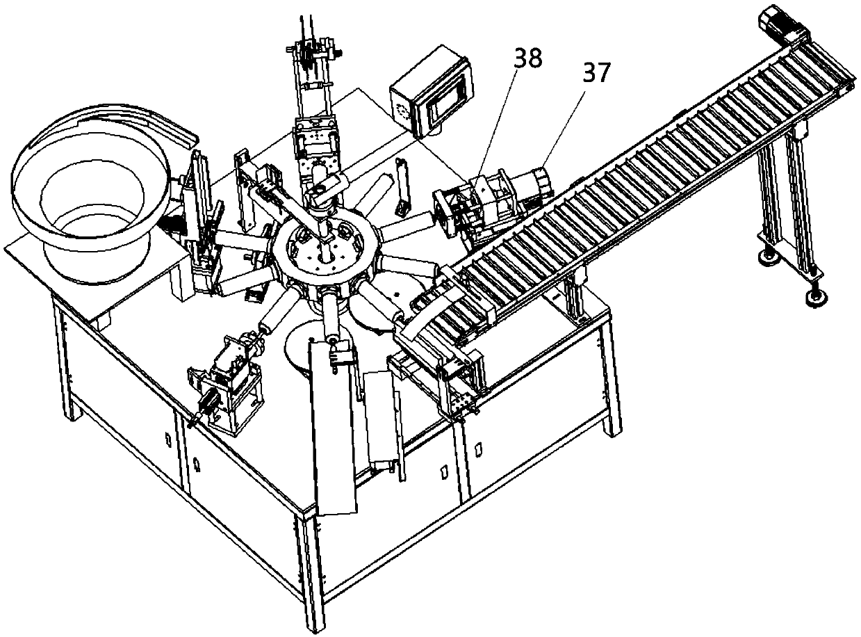
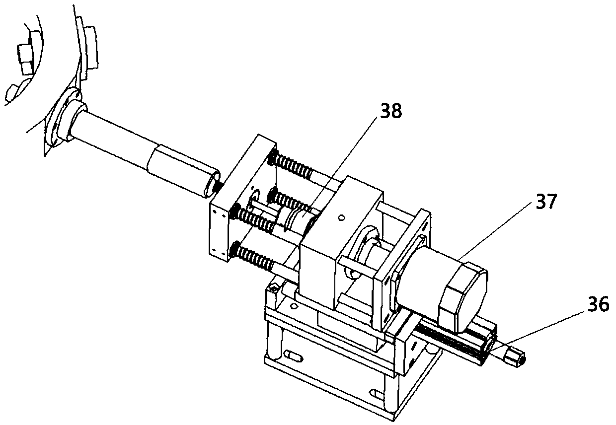
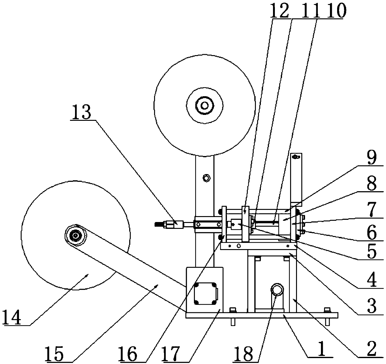
[0022] see Figure 1-8, a perforated film capping machine, including a chassis, the upper part of the chassis is provided with a workbench, the middle part of the workbench is provided with a work turntable, the work turntable is connected to a motor, the motor is fixed at the bottom of the workbench, and the work turntable is provided with a plurality of cards along the circumferential direction. Connecting part, the workbench is respectively provided with a ...


PUM


Abstract

The invention discloses a punching, film pasting and capping machine. The machine comprises a case, a punching mechanism comprises a punching air cylinder, the punching air cylinder is fixed to a mounting base, and a motor base is arranged on the upper portion of the mounting base and provided with a punching motor; the punching motor is connected with a punching rotation shaft through a motor shaft, the punching rotation shaft is connected with a punching drill bit, and a film pasting mechanism comprises a foil pasting baseplate; a first optical shaft is arranged on the foil pasting baseplate, the foil pasting baseplate is provided with a foil guide device, a left-right adjustment plate is connected to the upper portion of the first optical shaft, and the upper portion of the left-right adjustment plate is connected with the baseplate; an air cylinder fixing plate is arranged on the baseplate and provided with a slide rod, a slide plate is connected to the middle of the slide rod, anda lower die sleeve mounting plate is connected to the rear end of the slide rod. According to the punching, film pasting and capping machine, manual operation of workers is replaced by the machine, the operation difficulty is reduced to the minimum, the operation time is shortened, function maximization can be achieved, one-time completion can be achieved on the machine, and automation processingand production are achieved; the machine is easy to operate and high in efficiency, the manual cost is greatly lowered, the labor is saved, and the cost is reduced.

Description

technical field [0001] The invention relates to the technical field of capping machines, in particular to a perforating and film-attaching capping machine. Background technique [0002] The capping machine, also known as capping machine, capping machine and capping machine, is used for screwing and loosening the caps of plastic bottles and glass bottles (molded bottles or tube bottles). It is used for aluminum caps or aluminum-plastic caps crimping and sealing of antibiotic powder injection glass bottles (molded bottles or tube bottles), as well as packaging of beverage bottles. It is widely used in beverage and purified water industries. Currently, it is used in daily chemical, In the extruded tube hose and composite hose in the pharmaceutical and food industries, the perforated film lock cover of each hose is currently operated in a separate process. The hose is manually punched, and then moved to the aluminum foil paper. Paste on the tooth surface of the hose, and then m...

Claims


Application Information

Patent Timeline
IPC IPC(8): B67B3/20B67B6/00B26F1/16
CPCB26F1/16B67B3/2026B67B6/00B67B2201/06
Inventor 何永强
Owner 广东希顿智能机器有限公司
Why Eureka
Try Eureka