Supercharge Your Innovation With Domain-Expert AI Agents!

Geothermal-energy sludge drying equipment capable of automatically controlling temperature difference

A technology of geothermal energy and drying, which is applied in water treatment parameter control, water/sludge/sewage treatment, dehydration/drying/concentrated sludge treatment, etc., can solve the problems of temperature difference in the channel and affect the drying effect, and achieve Reduce the temperature difference, improve the effect, and the effect of uniform temperature

Active Publication Date: 2019-12-31
广东省福日升绿色科技研究有限公司
View PDF10 Cites 0 Cited by
  • Summary
  • Abstract
  • Description
  • Claims
  • Application Information

AI Technical Summary

Problems solved by technology

[0005] Aiming at the deficiencies of the prior art, the present invention provides a sludge geothermal energy drying equipment that can automatically control the temperature difference, which has the advantages of automatically controlling the temperature difference in the drying channel and improving the sludge drying effect, and solves the problem of sludge drying. During the process, there is a temperature difference inside the channel, which affects the drying effect

Method used


Image

  • Geothermal-energy sludge drying equipment capable of automatically controlling temperature difference
  • Geothermal-energy sludge drying equipment capable of automatically controlling temperature difference
  • Geothermal-energy sludge drying equipment capable of automatically controlling temperature difference

Examples


Embodiment Construction

[0028] The following will clearly and completely describe the technical solutions in the embodiments of the present invention with reference to the accompanying drawings in the embodiments of the present invention. Obviously, the described embodiments are only some of the embodiments of the present invention, not all of them. Based on the embodiments of the present invention, all other embodiments obtained by persons of ordinary skill in the art without making creative efforts belong to the protection scope of the present invention.

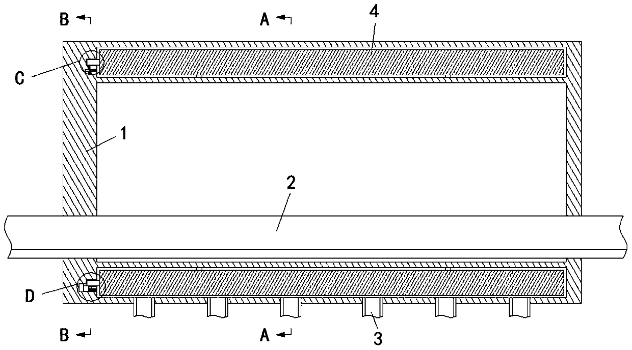
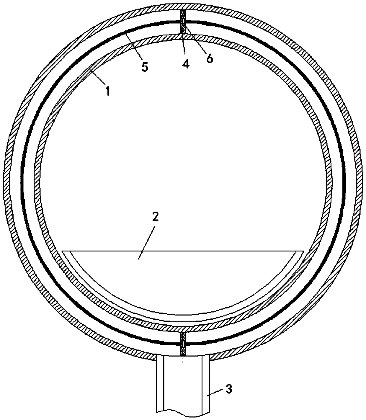
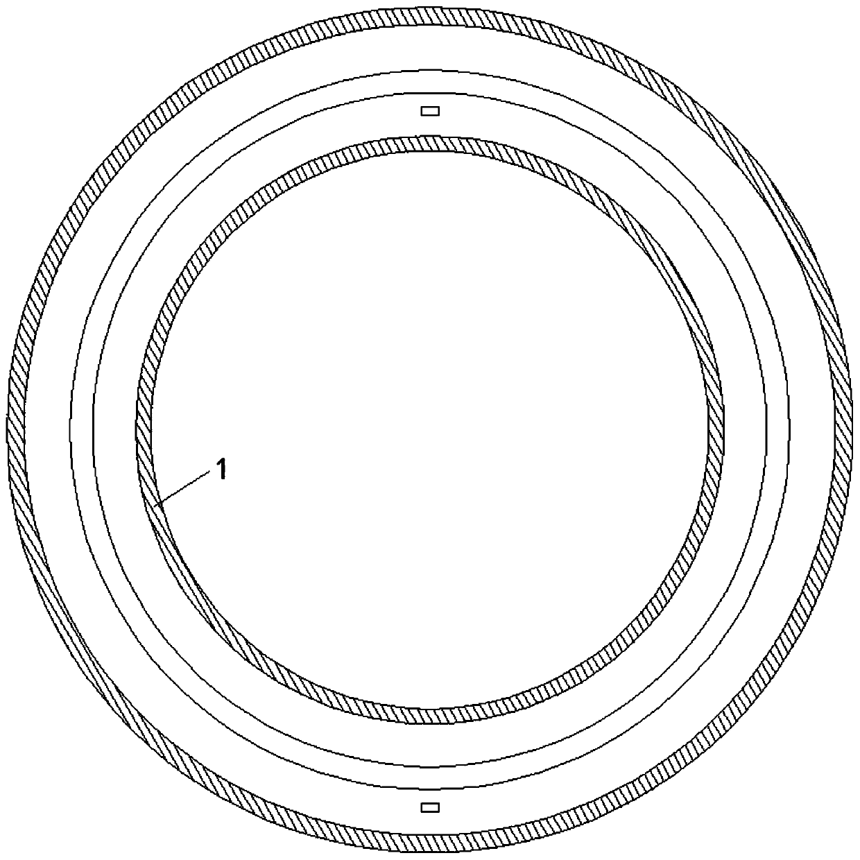
[0029] see Figure 1-9 , a sludge geothermal energy drying equipment that can automatically control the temperature difference, including a drying channel 1, a conveyor belt 2 is placed inside the drying channel 1, a geothermal energy heating pipe 3 is fixedly connected to the bottom of the drying channel 1, and the drying channel 1. There are two ventilating plates 4 connected to the inside of the barrel wall, and the two ventilating plates 4 ar...


PUM


Abstract

The invention relates to the technical field of geothermal energy equipment and discloses geothermal-energy sludge drying equipment capable of automatically controlling temperature difference. The geothermal-energy sludge drying equipment comprises a drying channel, wherein two air exchanging plates are movably connected to the interior of the cylinder wall of the drying channel; the two air exchanging plates are connected through a connecting ring; the left sides of the air exchanging plates are fixedly connected with inserting plates; an upper rotating plate and a lower rotating plate are rotatably arranged in and connected with the left wall of the drying channel; a pressure spring is installed on the lower rotating plate; and an upper thermal-deformation plate is fixedly installed on the left wall of the drying channel and located on the right side of the lower rotating plate. When hot air is just introduced, the upper thermal-deformation plate is heated to expand leftwards; the lower rotating plate is shifted by a push plate, so an upper collision ball collides with the inserting plates, and the air exchanging plate are allowed to rotate; air and heat respectively located in the upper and lower part of a hot air cavity exchange, so temperature is more uniform; when the inner temperature of the upper part of the hot air cavity decreases, the push plate moves rightwards, thelower rotating plate is shifted again, and such operations are cyclically repeated; so a temperature difference in a heating cavity is reduced, and sludge drying effect is improved.

Description

technical field [0001] The invention relates to the technical field of geothermal energy equipment, in particular to a sludge geothermal energy drying equipment that can automatically control the temperature difference. Background technique [0002] Geothermal energy is a renewable heat resource from the interior of the earth. It has the advantages of stability, reliability, low cost, clean and environmental protection, etc. It can be used for sludge drying. Sludge drying is through percolation or evaporation. A method to further reduce the moisture content of sludge. The odor, pathogens, and instability of the dried sludge have been significantly improved. It can be used as fertilizer, building materials, landfill, or further refining chemical products. Currently, domestic Sludge drying technologies mainly include new energy drying, equipment drying and new technology drying. As the earth's resources become increasingly tense, new energy drying technologies are getting more...

Claims


Application Information

Patent Timeline
IPC IPC(8): C02F11/13
CPCC02F11/13C02F2209/02
Inventor 管敏富
Owner 广东省福日升绿色科技研究有限公司
Features
  • R&D
  • Intellectual Property
  • Life Sciences
  • Materials
  • Tech Scout
  • Unparalleled Data Quality
  • Higher Quality Content
  • 60% Fewer Hallucinations
Learn More