Electromagnetic gun with segmented combination between guide rail and rifling

A technology of electromagnetic guns and guide rails, applied in the field of electromagnetic guns, can solve problems such as the inability to guarantee the flight stability and lethality of projectiles, and achieve the effects of increasing damage capabilities, increasing the range of projectiles, and avoiding the landing of projectile tails

Active Publication Date: 2019-12-31
NANJING UNIV OF SCI & TECH
View PDF6 Cites 9 Cited by
  • Summary
  • Abstract
  • Description
  • Claims
  • Application Information

AI Technical Summary

Problems solved by technology

The stability and lethality of the pro

Method used


Image

  • Electromagnetic gun with segmented combination between guide rail and rifling
  • Electromagnetic gun with segmented combination between guide rail and rifling
  • Electromagnetic gun with segmented combination between guide rail and rifling

Examples


Embodiment Construction

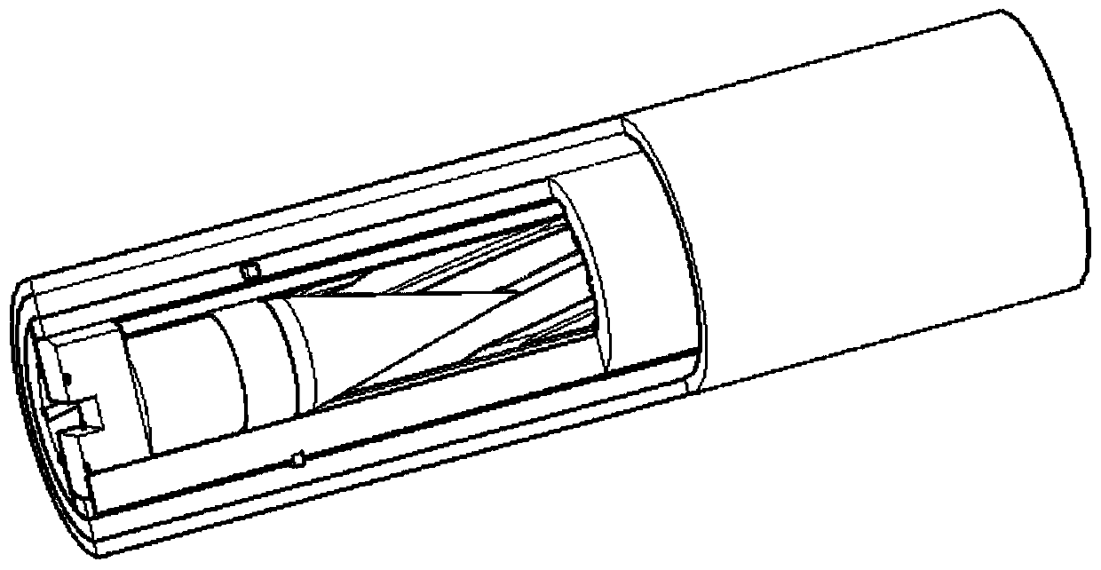
[0038] Such as Figure 1-10 As shown, a new structure of the railgun barrel enables the projectile to obtain rotational acceleration while obtaining linear acceleration in the bore, so that the projectile obtains greater rotational stability after being ejected from the muzzle, and increases the hit rate and damage capability of the projectile. The components of the structure mainly include the first rifled bore 3, the second rifled bore 4, the first electromagnetic guide rail 5, the second electromagnetic guide rail 6, the first insulating strip 9, the second insulating strip 10, the third insulating strip 11, the fourth Insulating strip 12, C-shaped shell stabilizing armature 8, bullet belt shell 7, stainless steel body tube 1, epoxy resin casting pre-tightening body, left front upper lock shaft, right front upper lock shaft, left rear upper lock shaft, right rear upper lock Shaft, Left Front Bottom Lock, Right Front Bottom Lock, Left Rear Bottom Lock, Right Rear Bottom Lock...


PUM


Abstract

The invention belongs to the field of electromagnetic emissions, and in particular relates to an electromagnetic gun with segmented combination between a guide rail and a rifling. The electromagneticgun comprises shells and bullet pivots, acceleration guide rails, rifling gun barrels, an insulation layer and a guide rail stable barrel, wherein the elastic pivots are rotatably connected with the shells; the acceleration guide rails comprise a first electromagnetic guide rail and a second electromagnetic guide rail which are oppositely arranged and have the same structure; the rifling gun barrels comprise a first rifling gun bore and a second rifling gun bore which are oppositely arranged and have the same structure; the two sides of the rifling gun bores are internally provided with symmetrical inclined rifling with the same rotation direction and the same winding degree, the inner diameter of the electromagnetic guide rails are larger than the inner diameter of the rifling gun barrelsand the two rifling gun bores and the two electromagnetic guide rails are staggered and vertically placed; the insulation layer is arranged between the acceleration guide rails and the rifling gun barrels to isolate the acceleration guide rails and the rifling gun barrels, so that the current flows only in the acceleration guide rail; and the guide rail stable barrel is arranged on the outer periphery of bore tubes. The structure of the electromagnetic gun enables the shells to obtain the linear acceleration in the bores and the obtain the rotation acceleration at the same time, so that theshell can obtain the larger rotation stability ability after the shells are shot out a muzzle, and the hit rate and damage ability of the shells are increased.

Description

technical field [0001] The invention belongs to the field of electromagnetic launch, and in particular relates to an electromagnetic gun combined with guide rails and rifling sections. Background technique [0002] An electromagnetic railgun is a weapon that uses electricity as its energy source to fire super-velocity projectiles. The railgun breaks through the limitation of traditional firearms and artillery in terms of launch principle, and changes from chemical energy drive to electric energy drive; this makes the limitation of the exit velocity of traditional artillery be lifted, that is, the electromagnetic railgun can obtain an exit velocity far exceeding that of traditional artillery. When the rail gun is working, the current flows through the guide rail, flows through the armature, returns to the guide rail, forms a strong magnetic field in the flowing area, and then pushes the armature to accelerate. [0003] In recent years, countries headed by the United States h...

Claims


Application Information

Patent Timeline
IPC IPC(8): F41B6/00
CPCF41B6/006
Inventor 李海元张威栗保明
Owner NANJING UNIV OF SCI & TECH
Why Eureka
Try Eureka