A CNC tool

A technology of blade and cutter body, applied in the direction of tools for lathes, manufacturing tools, accessories of tool holders, etc., can solve the problems of insufficient clamping force, reduce tool life, affect tool life, etc. The effect of tool life, tool cost reduction, and life extension

Active Publication Date: 2021-08-17
NANJING MEISHAN METALLURGY DEV
View PDF0 Cites 0 Cited by
  • Summary
  • Abstract
  • Description
  • Claims
  • Application Information

AI Technical Summary

Problems solved by technology

The above four blade fastening methods all have the same defect. There is only a single clamping force. When encountering strong cutting or intermittent cutting or different processing materials, the blade is easily damaged, thereby destroying the cutter body and reducing the service life of the cutter. The clamping blades are all made of hard alloy, which has the advantage of high hardness and good heat resistance, but the disadvantage is that the toughness is poor and not impact resistant, and the blade will break if it is slightly loose, which will also affect the service life of the tool; refer to the attached drawing Figure 1a , Figure 1b and Figure 1c , when there is only one kind of clamping force, the tool can only cut along the left direction. After the first cut is processed, the tool will return to the idle stroke, and then the second cutting will be performed after entering the tool, and so on until the processing meets the requirements. Dimensions; it can be seen that the cutting force is opposite to the clamping force, and the strength of a single clamping force is not enough, sometimes it cannot be realized. Even if some tools can cut, the cutting amount is very small and the processing efficiency is extremely low

Method used


Image

  • A CNC tool
  • A CNC tool
  • A CNC tool

Examples


Embodiment

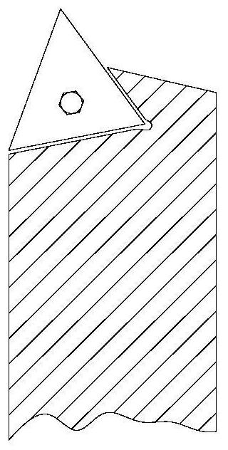
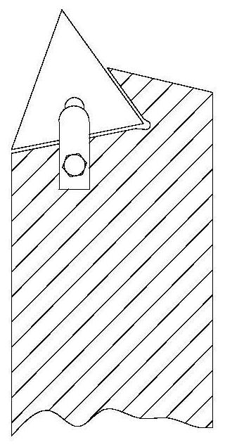
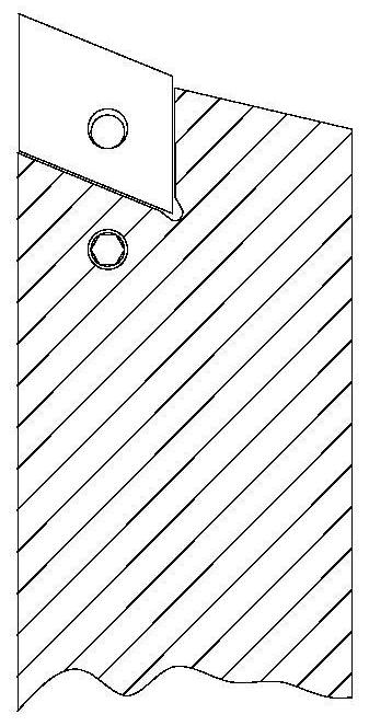
[0021] A kind of numerical control cutting tool of the present embodiment, such as figure 2 As shown, it includes a cutter body, a blade and a clamping part, and the clamping part includes a fixing nut, a pressing block for fixing the blade and a hook for fixing the blade; the front end of the cutter body is provided with The installation through hole is used for inserting the screw rod, the screw rod is provided with a V-shaped groove, the opening position of the V-shaped groove is matched with the hook head, the blade and the knife pad under the blade Pass through the hook head and lay flat in the knife groove of the cutter body. The pressing block is inserted into the upper end of the screw rod, and a fixing nut is arranged on the pressing block.

[0022] The bottom end of the screw rod is provided with a mounting hole, and the mounting hole is an inner hexagon.

[0023] The upper end of the screw is a flat structure.

[0024] The upper middle part of the screw rod has a...


PUM


Abstract

The invention relates to a numerically controlled cutting tool, which belongs to the technical field of using machine-clamped cutting tools in mechanical processing. The CNC cutting tool includes a cutter body, a blade and a clamping part. The clamping part includes a fixing nut, a pressing block for fixing the blade, and a hook for fixing the blade; the front end of the cutter body is provided with a mounting through hole, and the mounting through hole It is used to insert the screw. The screw is equipped with a V-shaped groove. The opening position of the V-shaped groove matches the hook head. The blade and the knife shim under the blade pass through the hook head and lay flat in the knife groove of the knife body. A pressing block is inserted into the upper end of the screw rod, and a fixing nut is arranged on the pressing block. The invention provides clamping force on the blade from two directions through the hook head and the pressing block to ensure that the blade will not loosen during use and maximize the service life of the tool. Compared with the previous method of clamping the blade with a single clamping force, the Under the same material and cutting environment, the service life of the tool is extended by two to three months on average, which significantly improves the service life of the tool and reduces the cost of the tool in machining.

Description

technical field [0001] The invention relates to a numerically controlled cutting tool, which belongs to the technical field of using machine-clamped cutting tools in mechanical processing. Background technique [0002] In the existing mechanical processing, there are four main methods of fastening the blade when using the clamping tool on the CNC machine tool. The first method is to use a screw to pass through the middle hole of the blade and directly fasten the blade with the screw, such as Figure 1a As shown, the service life of the tool is about four months on average; the second method is to screw on the knife body next to the blade, and fasten the blade by pressing the pads of different shapes with screws, such as Figure 1b As shown, the service life of the tool is about five months on average; the third method is to screw on the knife body next to the blade, use an L-shaped hook to hook the middle hole of the blade, and tighten the L-shaped hook with a screw. solid b...

Claims


Application Information

Patent Timeline
Patent Type & Authority Patents(China)
IPC IPC(8): B23B27/16
CPCB23B27/1625
Inventor 陈海平
Owner NANJING MEISHAN METALLURGY DEV
Why Eureka
Try Eureka