A wire feeding device for an automatic soldering machine

A technology of feeding device and soldering machine, which is applied in the direction of tin feeding device, auxiliary device, welding equipment, etc., can solve the problem of low efficiency of manual wire feeding, and achieve the effect of solving low efficiency and improving efficiency

Active Publication Date: 2022-02-22
湖南弘钧电子科技有限公司
View PDF6 Cites 0 Cited by
  • Summary
  • Abstract
  • Description
  • Claims
  • Application Information

AI Technical Summary

Problems solved by technology

[0004] The main purpose of the present invention is to provide a wire feeding device for an automatic soldering machine to solve the problem of low efficiency of manual wire feeding in the existing automatic soldering machine process

Method used


Image

  • A wire feeding device for an automatic soldering machine
  • A wire feeding device for an automatic soldering machine
  • A wire feeding device for an automatic soldering machine

Examples


Embodiment Construction

[0032] The following will clearly and completely describe the technical solutions in the embodiments of the present invention with reference to the accompanying drawings in the embodiments of the present invention. Obviously, the described embodiments are only part of the embodiments of the present invention, not all of them. Based on the embodiments of the present invention, all other embodiments obtained by persons of ordinary skill in the art without creative efforts fall within the protection scope of the present invention.

[0033] It should be noted that all directional indications (such as up, down, left, right, front, back...) in the embodiments of the present invention are only used to explain the relationship between the components in a certain posture (as shown in the accompanying drawings). Relative positional relationship, movement conditions, etc., if the specific posture changes, the directional indication will also change accordingly.

[0034] In addition, in t...


PUM


Abstract

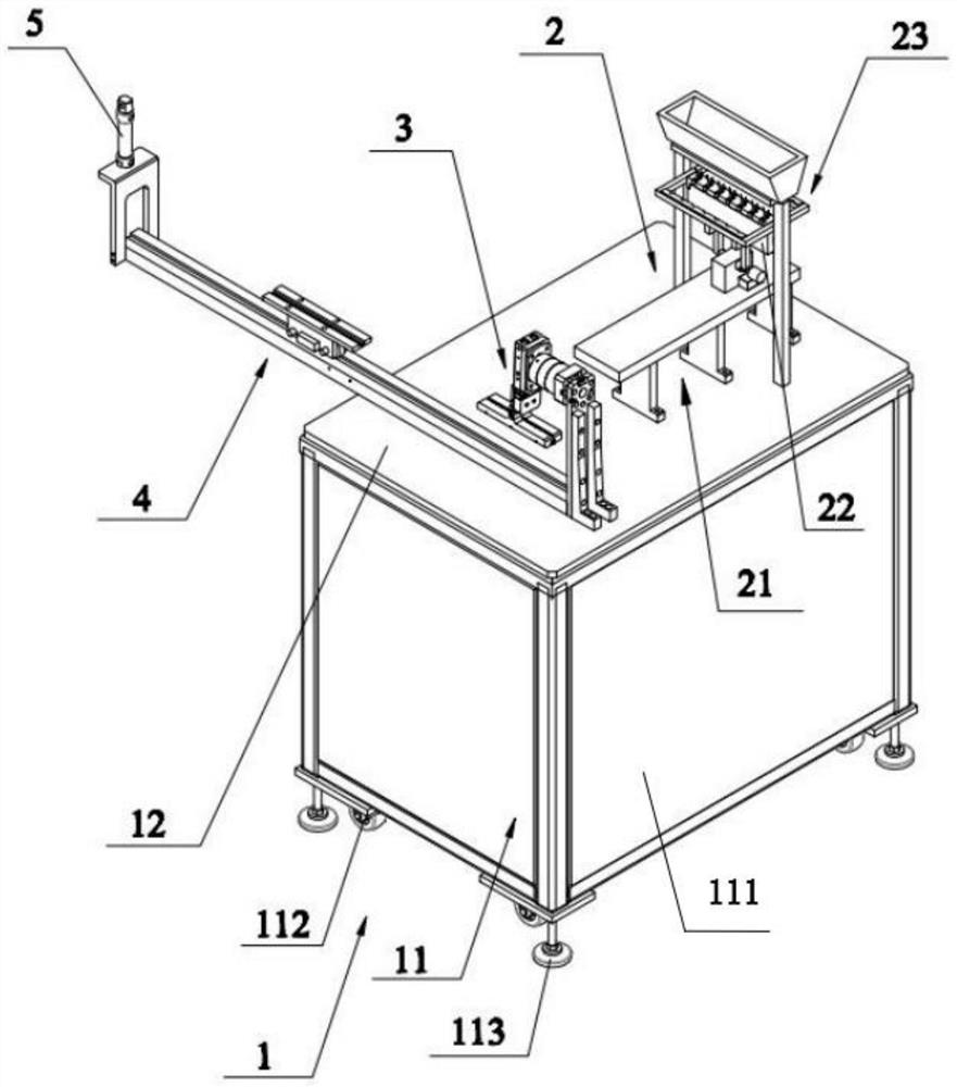
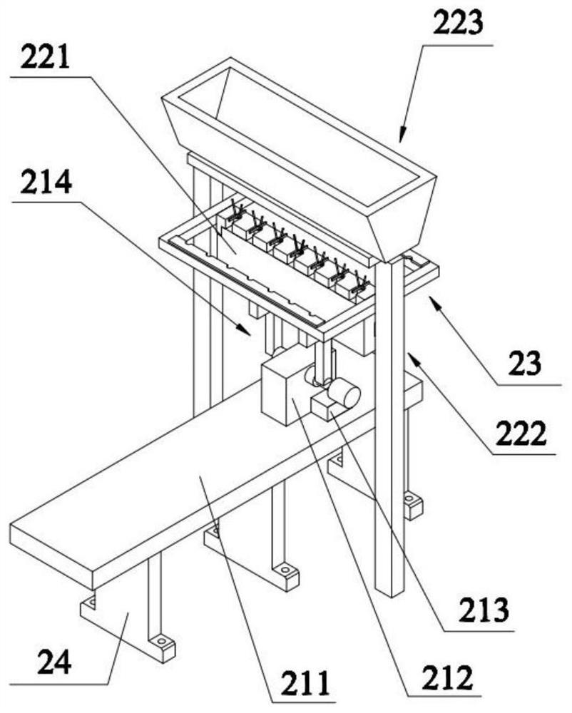
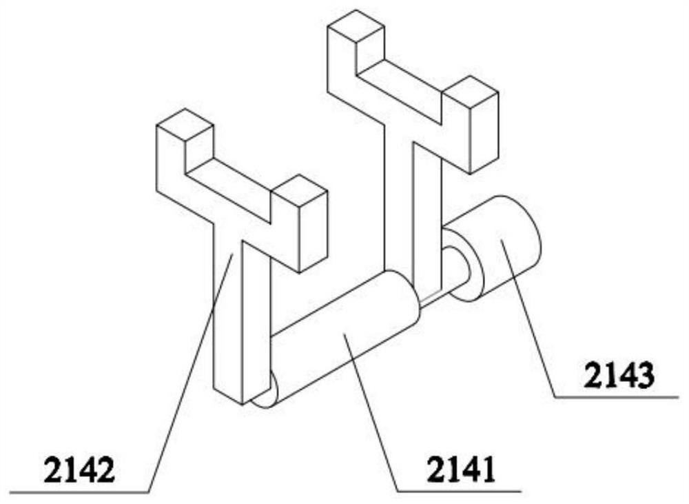
The invention discloses a wire feeding device for an automatic soldering machine, which comprises a support, a feeding part installed on the support, a transfer manipulator arranged at the discharge end of the feeding part, a guide rail seat arranged under the welding torch to dock the transfer manipulator, and the feeding part It includes a sliding seat fixed on the top of the support, a positioning seat connected to the sliding seat for positioning wires, and a wire clamp assembly connected to the positioning seat. The sliding seat is provided with a clamping manipulator, and the positioning seat is provided with a positioning plate for inserting and positioning wires. , the clamping manipulator is used to clamp the positioning plate of the positioned wire, the wire clamp assembly is used for peeling the wire and clamping the wire core that protrudes after the wire is peeled; the transfer manipulator is used to clamp the positioning plate and transfer it to the guide rail seat , the guide rail seat drives the positioning plate to move to the welding position of the welding torch. The wire to be welded is fixed on the positioning plate and the wire core is peeled and clamped by the wire clamp assembly. The transfer manipulator and guide rail seat complete the work of transferring the wire to the welding torch, realizing automatic feeding and improving the efficiency of wire feeding.

Description

technical field [0001] The invention relates to the field of automatic soldering machine devices, in particular to a wire feeding device for an automatic soldering machine. Background technique [0002] Today, intelligence and automation are common in people's lives, and machinery is no exception. With the development of all aspects of the country, automatic soldering machine technology continues to innovate. Soldering has changed from manual soldering to automatic soldering machines. Automatic soldering machine technology has become the industry's leading Mainstream trend, especially suitable for welding and docking of various electronic connectors, LED light strings, video and audio cable plugs, earphone cables, computer data cables, small circuit boards and small electronic components in the middle of the wiring harness. [0003] However, due to the lack of special feeding devices for automatic soldering machines, especially the wires used to connect various electronic co...

Claims


Application Information

Patent Timeline
Patent Type & Authority Patents(China)
IPC IPC(8): B23K3/06B23K3/08
CPCB23K3/06B23K3/08
Inventor 姚永红
Owner 湖南弘钧电子科技有限公司
Why Eureka
Try Eureka