Piston pin dismounting machine tool

A piston pin and machine tool technology, which is applied in the field of piston pin removal machine tools, can solve problems such as high labor intensity, and achieve the effect of reducing labor intensity and facilitating removal

Pending Publication Date: 2020-01-03
ANHUI SCI & TECH UNIV
View PDF0 Cites 2 Cited by
  • Summary
  • Abstract
  • Description
  • Claims
  • Application Information

AI Technical Summary

Problems solved by technology

[0003] The technical problem to be solved by the present invention is to provide a piston pin removal machine tool to solve the technical problem in the prior art that manual removal of the piston pin requires multiple knocks to remove it, and the labor intensity is high

Method used


Image

  • Piston pin dismounting machine tool
  • Piston pin dismounting machine tool
  • Piston pin dismounting machine tool

Examples


Embodiment Construction

[0026] In order to make the object, technical solution and advantages of the present invention clearer, the present invention will be further described in detail below in conjunction with the accompanying drawings and embodiments. It should be understood that the specific embodiments described here are only used to explain the present invention, not to limit the present invention.

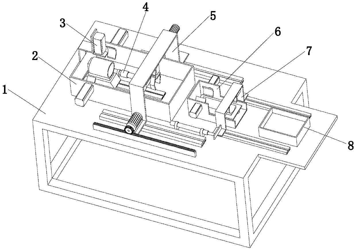
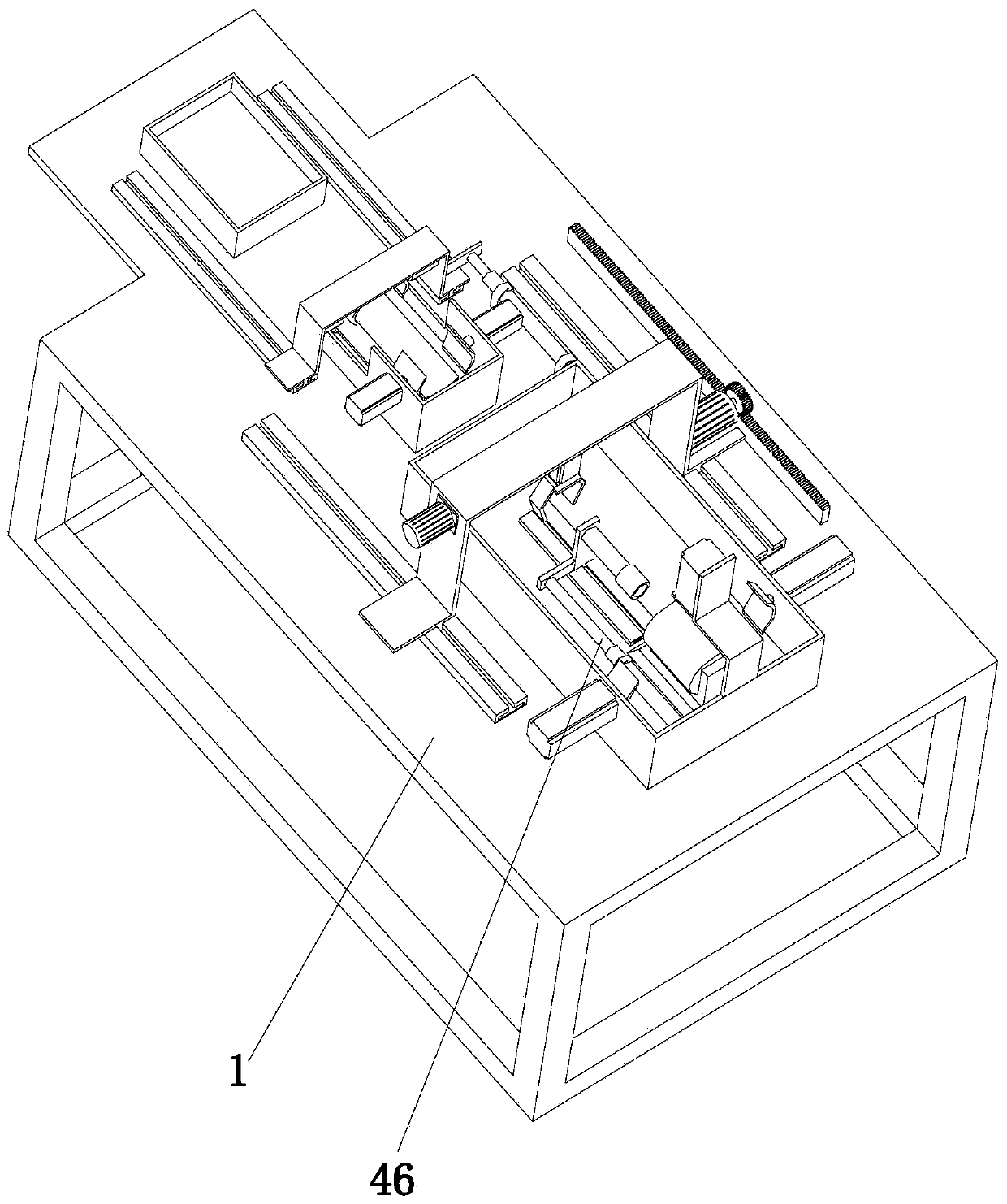
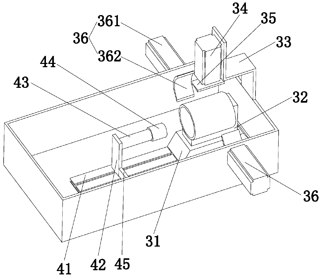
[0027] refer to Figure 1 to Figure 6It can be seen that the present invention provides a piston pin removal machine tool, including a frame 1, a primary disassembly frame 2, a positioning and clamping assembly 3, a primary disassembly assembly 4, a conveying assembly 5, a secondary disassembly placement frame 6, and a secondary disassembly assembly 7 and a piston pin placement frame 8, the frame 1 is arranged on the ground, the first disassembly placement frame 2 is arranged on one end of the top of the frame 1, the positioning and clamping assembly 3 and the initial disassembly assembly 4 is arr...


PUM


Abstract

The invention discloses a piston pin dismounting machine tool, and belongs to the technical field of piston pin dismounting. The piston pin dismounting machine tool comprises a machine frame, a primary disassembling placement frame, a positioning clamping assembly, a primary disassembling assembly, a conveying assembly, secondary disassembly placement frame, the secondary disassembling assembly and a piston pin placement frame, wherein the frame is arranged on the ground, the primary disassembly placement frame is arranged on the top of the machine frame on one end, the positioning clamping assembly and the primary disassembling assembly is disposed in the inner of the primary disassembling placement frame, the secondary disassembly placement frame is arranged on the side of the primary disassembling placement frame, and the conveying assembly is arranged in the first disassembling placement frame and the secondary disassembling placement frame, the piston pin placement frame placingframe is arranged on the side of the secondary disassembling placement frame, and the secondary disassembling assembly is arranged between the secondary disassembly placement frame and the piston pin.According to the piston pin dismounting machine tool, the problems of manual disassembly and high labor intensity of manual disassembly of the piston pin are solved.

Description

technical field [0001] The invention relates to the technical field of piston pin removal, in particular to a piston pin removal machine tool. Background technique [0002] The piston and connecting rod group is one of the important moving parts in the diesel locomotive diesel engine. The connecting rod and the piston are connected by the piston pin. The connecting rod converts the linear reciprocating motion of the piston into the rotary motion of the crankshaft and transmits it between the piston and the crankshaft. Force: There is a clearance fit between the piston pin and the bushing of the small end hole of the connecting rod, and a transition fit between the piston pin and the pin hole of the piston. When assembling the piston and connecting rod, heat the piston to 100-120°C in an oven, place the small end of the connecting rod in the piston, and then assemble the piston pin into the hole of the piston pin seat. When the diesel engine is overhauled or the car is scrap...

Claims


Application Information

Patent Timeline
IPC IPC(8): B25B27/02
CPCB25B27/026
Inventor 张春雨黄丹丹鲍官培乔印虎郑凤菊
Owner ANHUI SCI & TECH UNIV
Why Eureka
Try Eureka