a marine propeller

A technology for propulsion and marine applications, applied in ship propulsion, propulsion components, ship construction, etc., can solve the problems of limited water injection, large rear space occupation, vibration and noise problems, etc., to reduce shafting transmission and facilitate overall layout. , the effect of easy structure design

Active Publication Date: 2021-08-31
708TH RES INST OF CSSC
View PDF10 Cites 0 Cited by
  • Summary
  • Abstract
  • Description
  • Claims
  • Application Information

AI Technical Summary

Problems solved by technology

[0002] As the most important way of water transportation and operation, ships have always been developing towards functionalization, speed and large-scale development. In recent years, due to the increase in international trade and the growth of marine resource exploitation, the demand for ships' navigation speed indicators has become more and more However, as the size of the ship becomes larger and larger, the performance of the propeller is more and more restricted, and the speed of the ship has not been effectively improved. Moreover, the propeller needs to continuously cut the fluid during the propulsion process, so it is inevitable and prone to The blade cavitation problem of the propeller, and the resonance problem at the tail of the hull caused by the cutting frequency of the blade. On the other hand, since the propeller requires a large amount of shafting transmission, and the frequency of the blade works together, vibration and noise problems of multiple frequencies are more likely to occur, and It takes up a lot of space at the tail, which brings great difficulties to the overall layout and structural design. Therefore, it is necessary to propose a marine propeller to solve the various drawbacks of traditional ship propellers
[0003] The traditional form of the propeller is that the blades rotate to generate a pressure difference to propel the ship forward. In recent years, the water jet propulsion technology has been developed to a certain extent. However, due to the limitation of the amount of water sprayed, the high-speed jet of water will produce cavitation and air bubbles. Therefore, water jet propulsion technology is generally applied to small civilian ships, and it is difficult to be widely used on ships.

Method used


Image

  • a marine propeller
  • a marine propeller
  • a marine propeller

Examples


Embodiment Construction

[0032] The following will clearly and completely describe the technical solutions in the embodiments of the present invention with reference to the accompanying drawings in the embodiments of the present invention. Obviously, the described embodiments are only some, not all, embodiments of the present invention. Based on the embodiments of the present invention, all other embodiments obtained by persons of ordinary skill in the art without creative efforts fall within the protection scope of the present invention.

[0033] It should be noted that, in the case of no conflict, the embodiments of the present invention and the features in the embodiments can be combined with each other.

[0034] The present invention will be further described below in conjunction with the accompanying drawings and specific embodiments, but not as a limitation of the present invention.

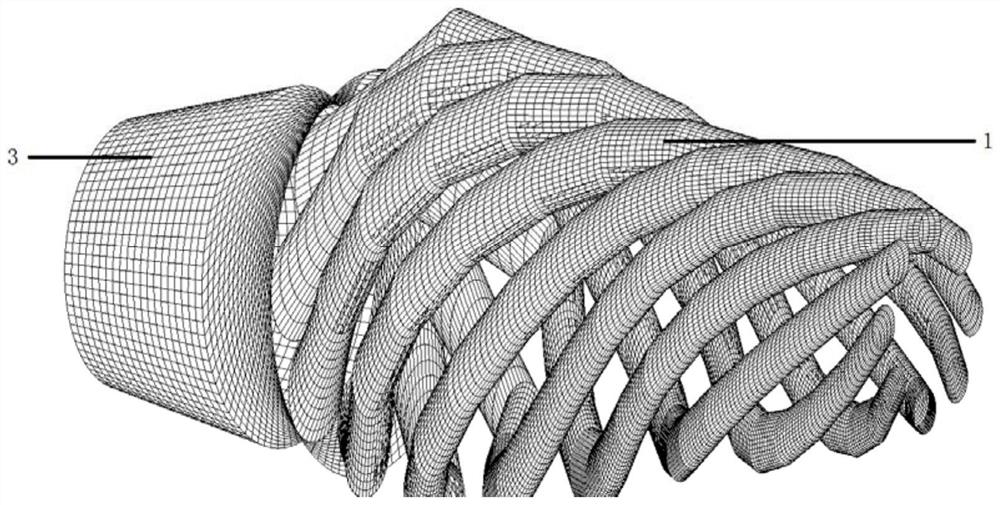
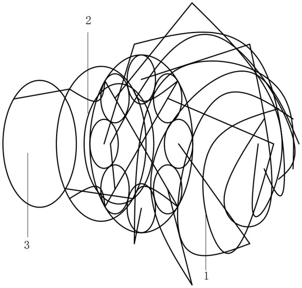
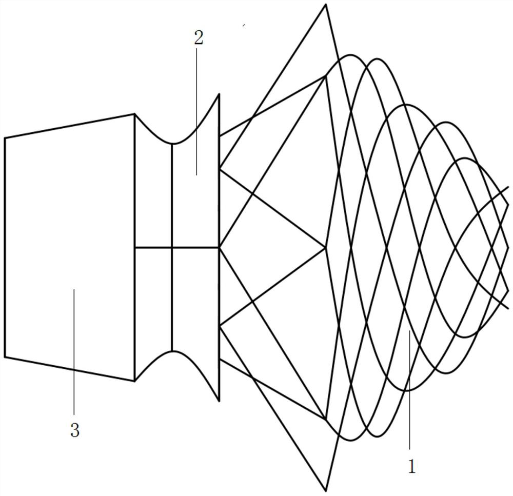
[0035] refer to Figure 1-13 A structural diagram of a marine propeller provided by the present invention, comp...


PUM


Abstract

The present invention relates to the technical field of ships and ocean engineering, in particular to a marine propeller, comprising: a diversion pipe, a rectification pipe, and an injection pipe; the diversion pipe includes a predetermined number of pipes, and the predetermined number of pipes The length direction is spirally wound, and the inner side of each pipeline is provided with a plurality of water suction holes; the rectification pipeline is fixedly connected with the guide pipeline, and the rectification pipeline includes an inflow section, an enveloping circle and a rectification opening; The pipeline is fixedly connected with the rectifying pipeline, and the injection pipeline is a cylinder whose section gradually shrinks from the inlet to the outlet. The invention greatly increases the amount of water sprayed by the propeller, and the thrust is effectively improved; the water spray is more stable, no cavitation phenomenon occurs, no noise, no vibration, and the comfort of the ship is improved; shafting transmission is reduced, and space is occupied Greatly reduced, easy for overall layout and structural design; the injection speed is within a predetermined range, and there will be no cavitation.

Description

technical field [0001] The invention relates to the technical field of ships and marine engineering, in particular to a marine propeller. Background technique [0002] Ships, as the most important means of water transportation and operations, have always been developing towards functionalization, speed and large-scale. In recent years, due to the increase in international trade and the growth of marine resource exploitation, the demand for ships' navigation speed indicators has become more and more However, as the size of the ship becomes larger and larger, the performance of the propeller is more and more restricted, and the speed of the ship has not been effectively improved. Moreover, the propeller needs to continuously cut the fluid during the propulsion process, so it is inevitable and prone to The blade cavitation problem of the propeller, and the resonance problem at the tail of the hull caused by the cutting frequency of the blade. On the other hand, since the propel...

Claims


Application Information

Patent Timeline
Patent Type & Authority Patents(China)
IPC IPC(8): B63H11/02
CPCB63H11/02
Inventor 周佳张海彬李成君王璞
Owner 708TH RES INST OF CSSC
Why Eureka
Try Eureka